Ac LED dimmer and dimming method thereby

a technology of led dimmer and dimming method, which is applied in the direction of electric variable regulation, process and machine control, instruments, etc., can solve the problems of limited operating range of phase control scheme and traditional dimming method using triac, restrictive function used in practice, and ac led to flicker

Active Publication Date: 2010-03-11
SEOUL SEMICONDUCTOR
View PDF13 Cites 73 Cited by
  • Summary
  • Abstract
  • Description
  • Claims
  • Application Information

AI Technical Summary

Benefits of technology

[0020]Exemplary embodiments of the present invention also provide an improved AC LED dimmer and dimming method capable of reducing or minimizing flickering of the AC LED caused by the insufficient operating margin of the resistor and capacitor of the R / C phase controller in the conventional dimmer.

Problems solved by technology

In general, a lamp may have a dimming function that allows a user to control brightness of the lamp, but such a function has been restrictively used in practice.
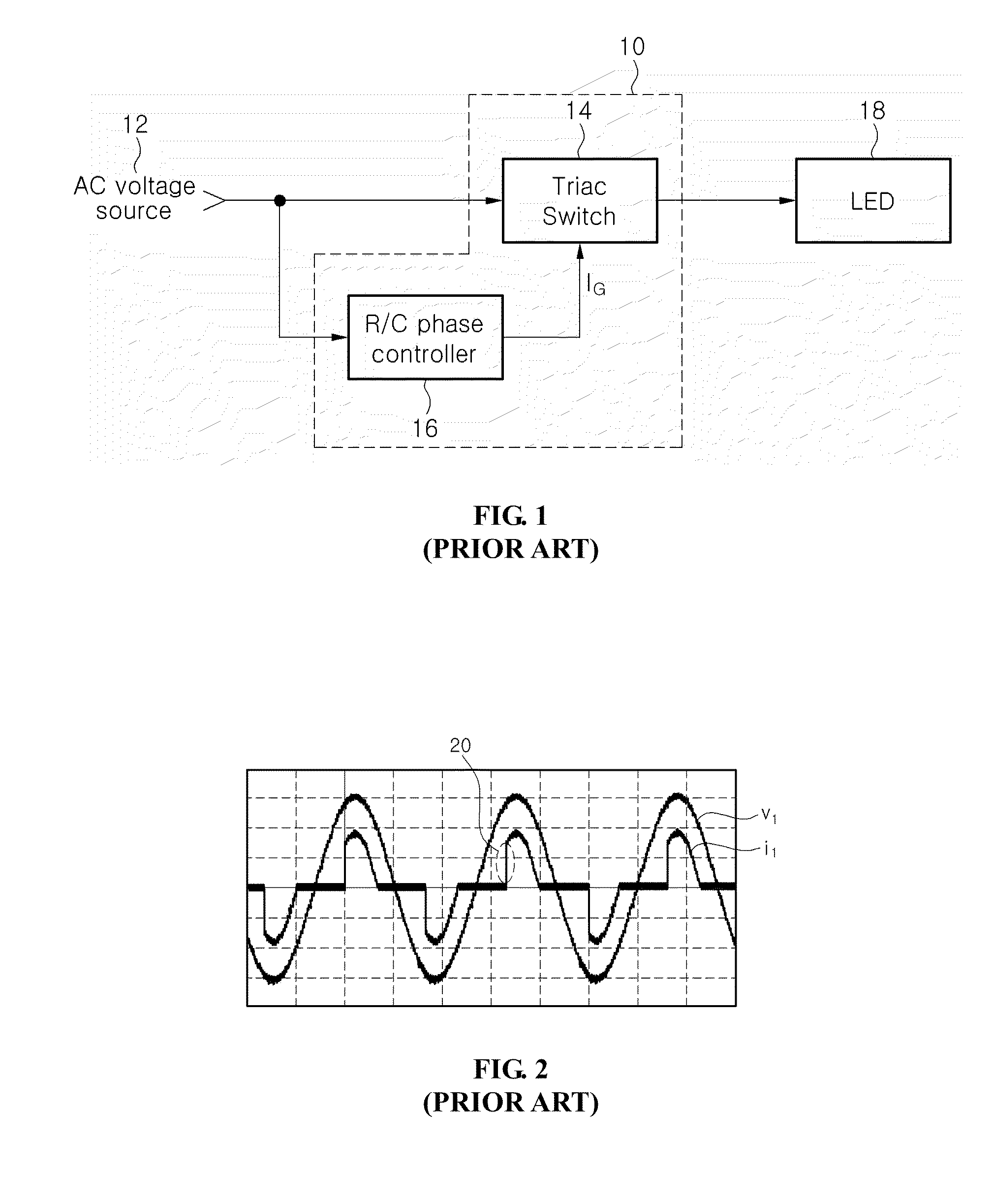
However, the phase control scheme and the traditional dimming method using the Triac are limited in terms of operating range due to a controller configured to drive the Triac and inherent characteristics of the Triac.
An insufficient operating margin may cause the gate turn-on signal IG (see FIG. 1) to instantaneously flow, thereby causing the AC LED to flicker.
As such, there is a problem in that a minimum dimming range and a maximum dimming range are very limited due to the drive voltage of the Triac and the characteristics of the resistor and capacitor of the R / C phase controller.

Method used


Image

  • Ac LED dimmer and dimming method thereby
  • Ac LED dimmer and dimming method thereby
  • Ac LED dimmer and dimming method thereby

Examples


Embodiment Construction

[0040]The invention is described more fully hereinafter with reference to the accompanying drawings, in which embodiments of the invention are shown. This invention may, however, be embodied in many different forms and should not be construed as limited to the embodiments set forth herein. Rather, these embodiments are provided so that this disclosure is thorough, and will fully convey the scope of the invention to those skilled in the art. In the drawings, the size and relative sizes of layers and regions may be exaggerated for clarity. Like reference numerals in the drawings denote like elements.

[0041]It will be understood that when an element or layer is referred to as being “on” or “connected to” another element or layer, it can be directly on or directly connected to the other element or layer, or intervening elements or layers may be present. In contrast, when an element or layer is referred to as being “directly on” or “directly connected to” another element or layer, there a...


PUM


Abstract

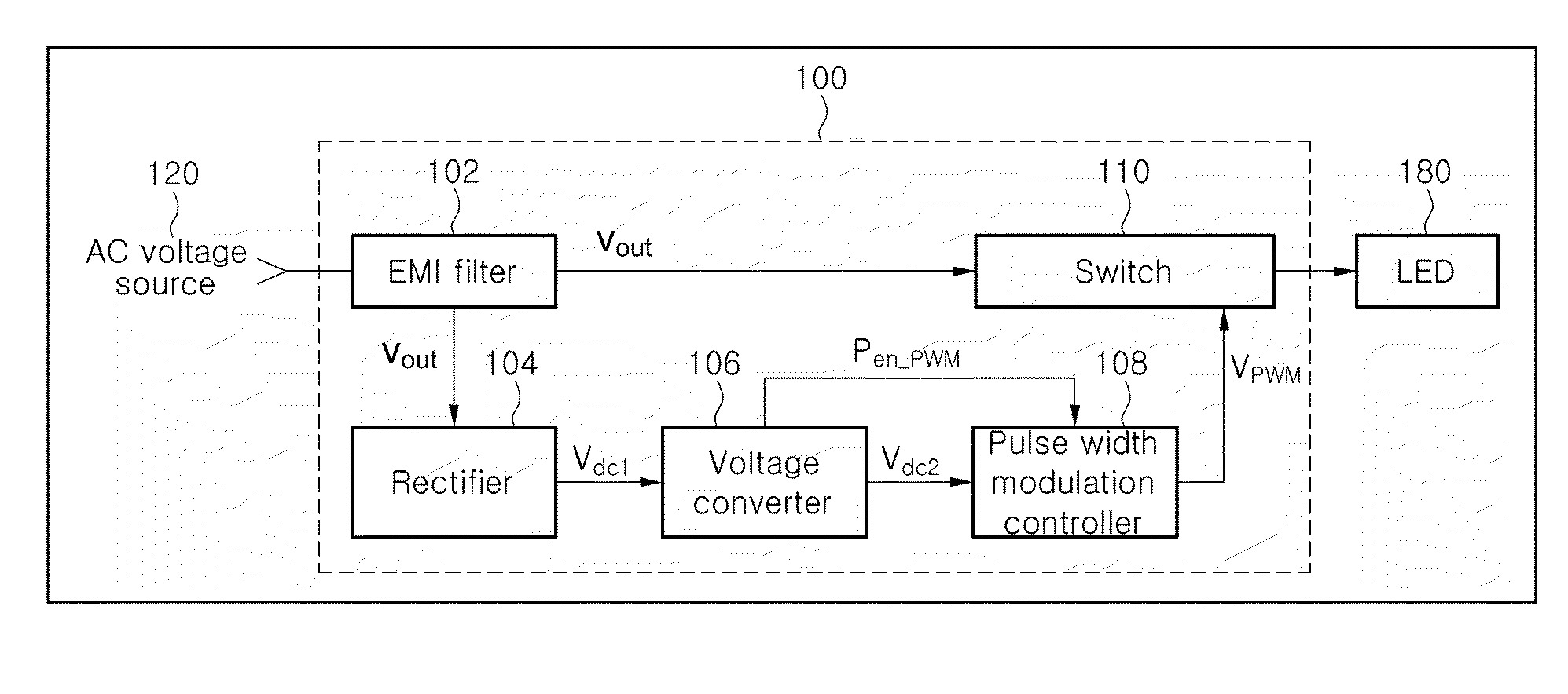
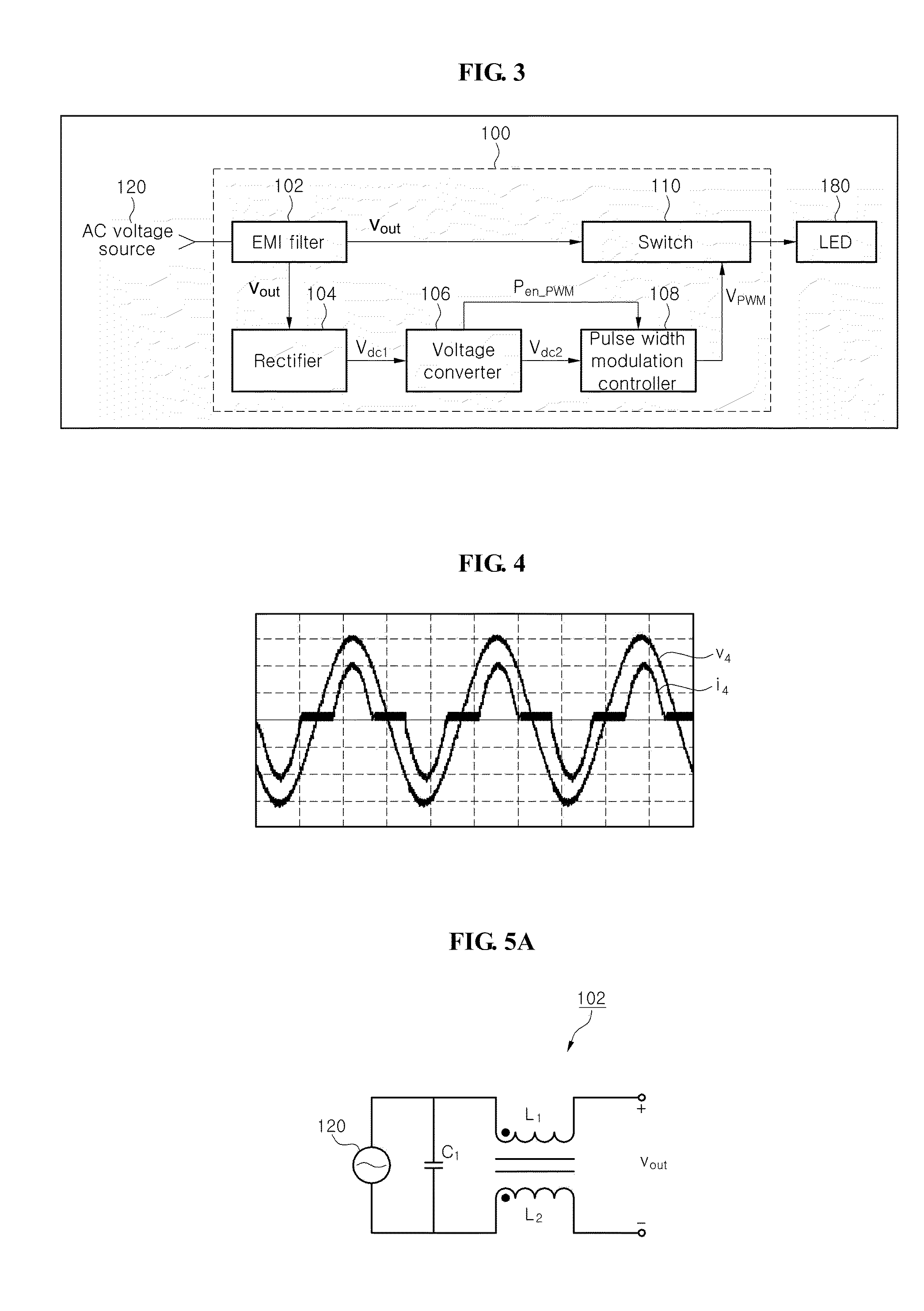
The disclosure relates to an AC LED dimmer and dimming method thereof. The AC LED dimmer includes a rectifier receiving AC voltage from an AC voltage source and full-wave rectifying the AC voltage; a direct current (DC) / DC converter receiving the full-wave rectified voltage from the rectifier, generating a full-wave rectified stepped-up voltage, and generating a pulse enable signal; a pulse width modulation controller receiving the full-wave rectified stepped-up voltage and generating a pulse width modulation signal to dim an AC LED in response to the pulse enable signal; a switch driving the AC LED under control of the pulse width modulation signal, and an electromagnetic interference (EMI) filter to be connected between the AC voltage source and the switch to eliminate electromagnetic interference from the AC voltage source. Accordingly, the dimmer can perform an efficient and linear dimming function and suppress harmonics.

Description

CROSS REFERENCE TO RELATED APPLICATION[0001]This application claims priority from and the benefit of Korean Patent Application No. 10-2008-0087758, filed on Sep. 5, 2008, which is hereby incorporated by reference for all purposes as if fully set forth herein.BACKGROUND OF THE INVENTION[0002]1. Field of the Invention[0003]Exemplary embodiments of the present invention relate to an alternating current (AC) light-emitting diode (LED) dimmer and a dimming method thereby and, more particularly, to an AC LED dimmer which performs a dimming function of an AC LED by bidirectionally switching AC voltage at a high speed under control of a pulse width modulation signal, and a dimming method thereby.[0004]2. Discussion of the Background[0005]In general, a lamp may have a dimming function that allows a user to control brightness of the lamp, but such a function has been restrictively used in practice. As energy saving has become an important concern in association with an increase in electrical ...

Claims


Application Information

Patent Timeline
Patent Type & Authority Applications(United States)
IPC IPC(8): H05B37/02H05B44/00
CPCH05B33/0809H05B37/02Y02B20/346H05B33/0815Y02B20/30H05B45/382H05B45/10
Inventor CHOI, BYUNG HOONPARK, IN KYU
Owner SEOUL SEMICONDUCTOR
Why Eureka
Try Eureka