Self destruction impact fuse

Active Publication Date: 2010-04-15
ADVANCED MATERIAL ENG PTE
View PDF11 Cites 1 Cited by
  • Summary
  • Abstract
  • Description
  • Claims
  • Application Information

AI Technical Summary

Benefits of technology

[0007]One embodiment of the present invention provides a self destructing impact fuze employed in a low velocity projectile for detonating explosive charge coupled thereto. The self destructing impact fuze comprises a frame, a self destructing (SD) firing pin assembly disposed concentrically within said frame, said SD firing pin assembly comprising a SD head on one end for receiving a SD spring, a SD firing pin on the opposite end for striking a detonator, and a centrifugal chamber for holding a plurality of spheres therein, said chamber further communicating with a plurality of radial openings and exposing portion of said spheres when the fuze is spun, a groove disposed on the surface of said SD firing pin assembly for receiving two centrifugal locks, said locks having a pivot offset from the longitudinal axis of said frame and having a symmetric configuration, a setback pin assembly for each of the centrifugal lock

Problems solved by technology

However, when ammunition with an impact fuze is delivered, it may fail to explode due to insufficient impact.
Unexploded ammunition poses hazards for the civilians and the military alike and operation to remove such unexploded ammunition is dangerous, costly and labor intensive.
However, the disclosed self destructing impact fuze is not functioning as well in low velocity projectiles as in high velocity projectiles.

Method used


Image

  • Self destruction impact fuse
  • Self destruction impact fuse
  • Self destruction impact fuse

Examples


Embodiment Construction

[0021]The present invention may be understood more readily by reference to the following detailed description of certain embodiments of the invention.

[0022]Throughout this application, where publications are referenced, the disclosures of these publications are hereby incorporated by reference, in their entireties, into this application in order to more fully describe the state of art to which this invention pertains.

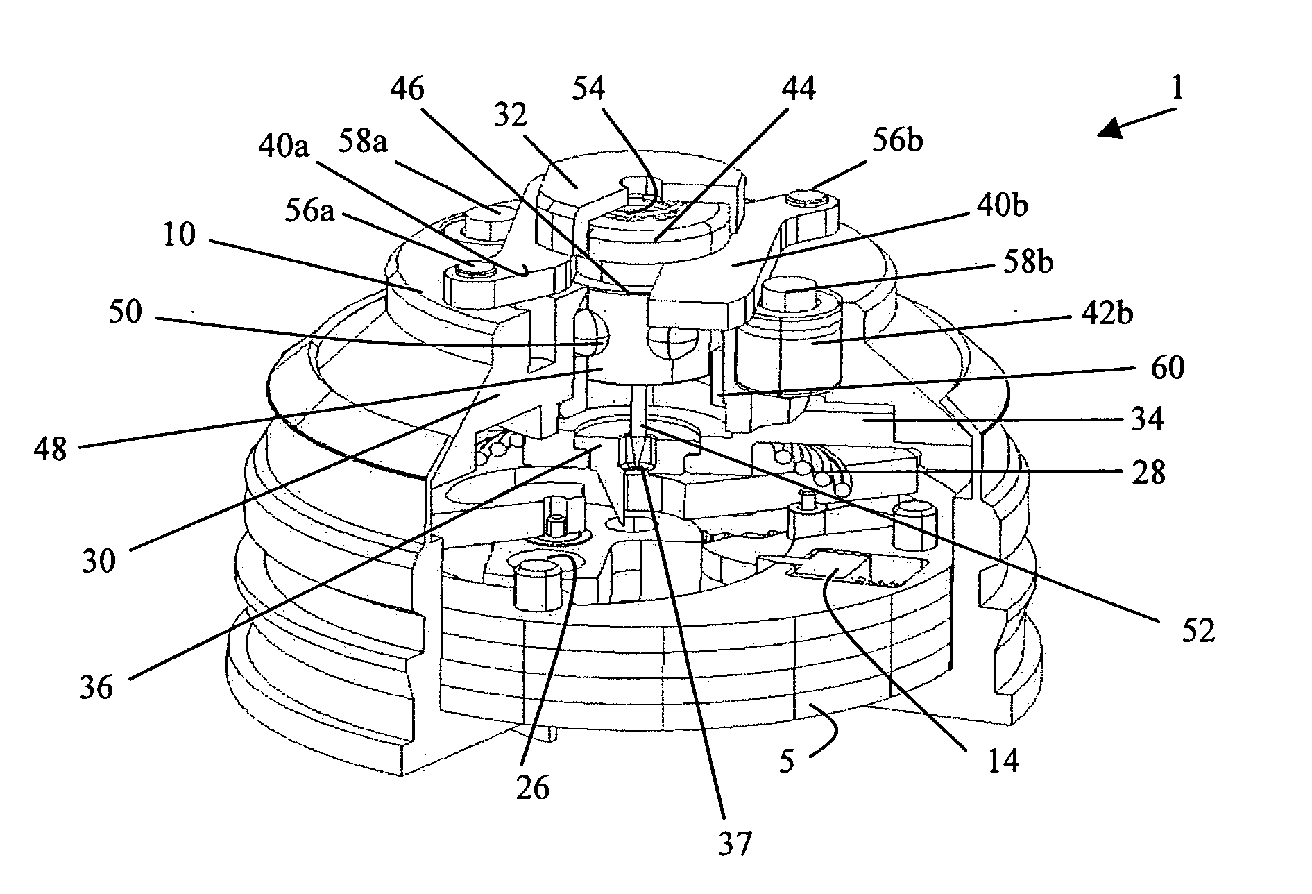
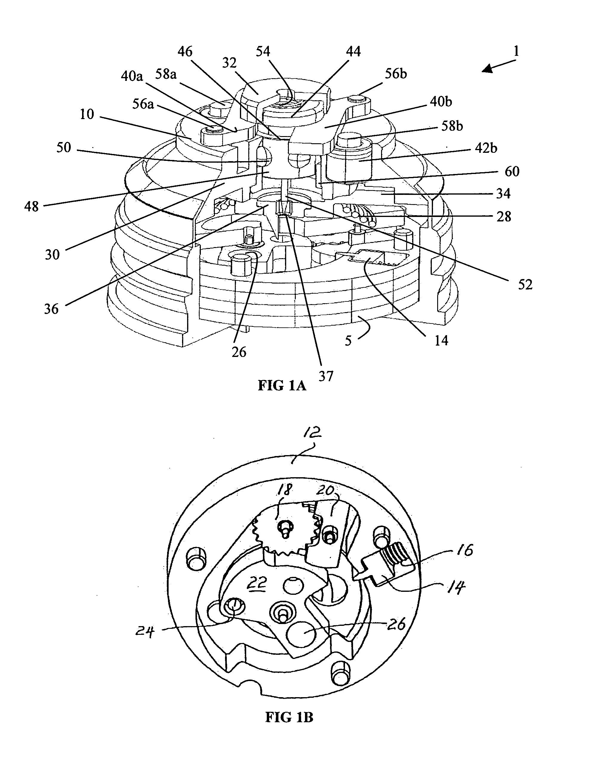
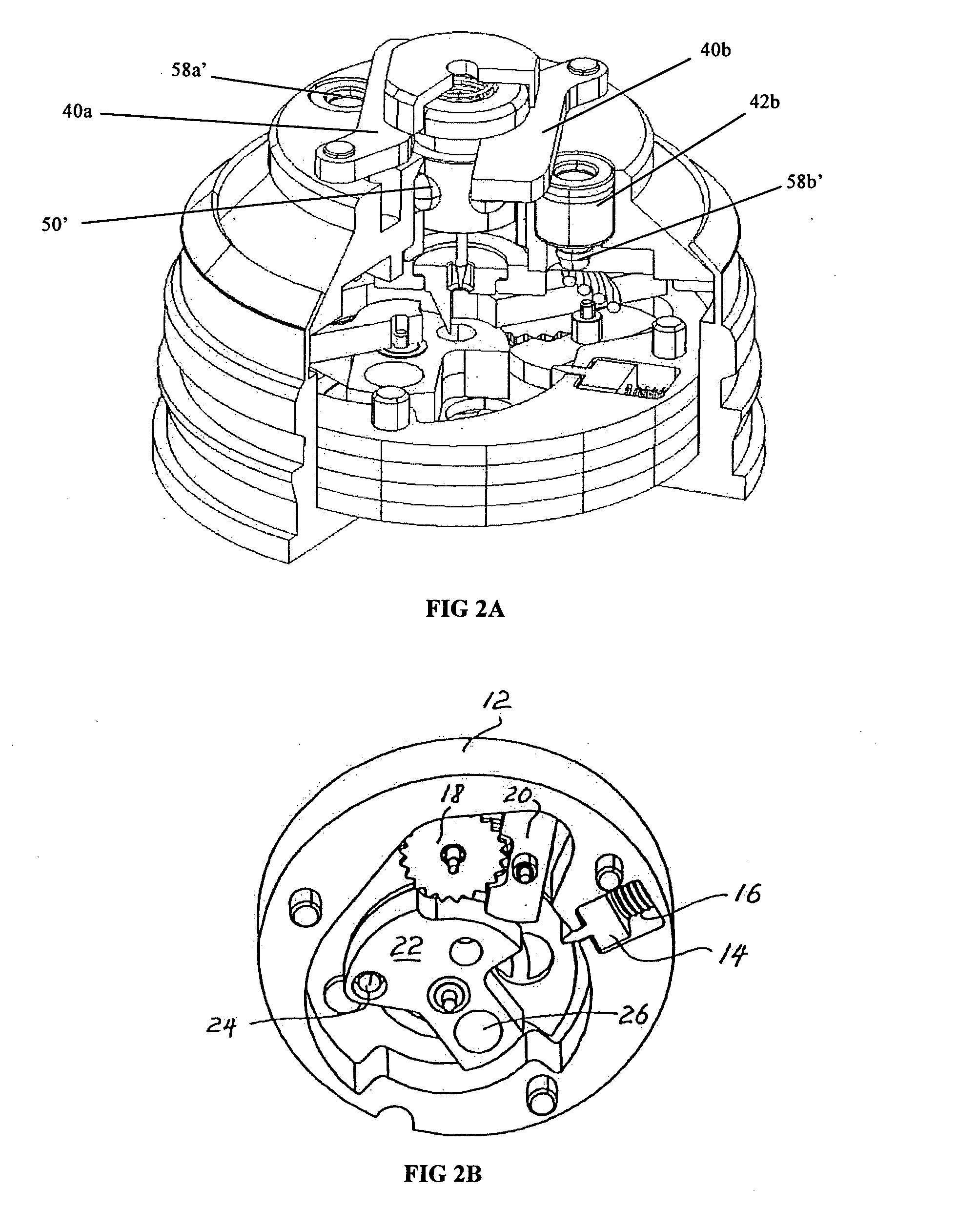
[0023]In the following detailed description, specific details are set forth in order to provide a thorough understanding of the invention. However, in the following description, numerous specific details are set forth such as centrifugal chamber and firing pin in order to provide a thorough understanding of the present invention. It will be obvious to one skilled in the art that the present invention may be practiced without these specific details. In other instances, description of well-known parts such as those involved with explosive charges and the external structur...


PUM


Abstract

The present invention provides a self destruction impact fuse for fail-proof detonating a projectile, preferably a low velocity projectile. The present invention further provides a projectile that can be detonated reliably even at low velocity.

Description

FIELD OF THE INVENTION[0001]The present invention generally relates to the technologies of ammunition detonation, and more particularly to a self destructing impact fuze that can detonate ammunition reliably when the ammunition is delivered by projectiles, especially the low velocity projectiles.BACKGROUND OF THE INVENTION[0002]Ammunition comprises two main components, namely projectile and primed cartridge case; the projectile further comprises a fuze and shell body. One type of fuzes commonly used in ammunition is impact fuze that detonates the ammunition by the resultant impact from the hitting of the ammunition to its target. However, when ammunition with an impact fuze is delivered, it may fail to explode due to insufficient impact. The insufficient impact may be caused by a variety of reasons including: (1) it misses the target and lands on soft grounds such as a swamp or a snow covered area; or (2) it lands on a suboptimal angle with respect to the point of impact. Unexploded...

Claims


Application Information

Patent Timeline
IPC IPC(8): F42C9/18F42C15/188F42C15/22
CPCF42C9/18F42C15/26F42C15/22F42C15/188F42C15/20
Inventor AW, CHENG HOKQUEK, JUAN KIATSIE, SOO CHEW
Owner ADVANCED MATERIAL ENG PTE
Why Eureka
Try Eureka