Optical Fiber Management Shelf for Optical Connection Terminals

a technology of optical fiber management and optical connection terminals, applied in the direction of optics, mountings, instruments, etc., can solve the problems of increased installation time, cost and maintenance, and increased complexity of fiber optic networks, and achieve the effect of reducing installation time, cost and maintenance, and increasing installation tim

Inactive Publication Date: 2010-04-15
CORNING CABLE SYST LLC
View PDF101 Cites 57 Cited by
  • Summary
  • Abstract
  • Description
  • Claims
  • Application Information

AI Technical Summary

Benefits of technology

[0015]An inner wall protects the optical fibers from falling through the access opening. An outer wall formed on the edges of the platform protects the optical fibers from falling into the base along a side of the base. The shelf also includes a routing area on the top side positioned at least partially around the access opening and adapted for routing slack in the optical fib

Problems solved by technology

To facilitate this capacity and reach, the fiber optic networks must employ additional fiber optic cable, hardware and components resulting in increased installation time, cost and maintenance.
This results in the fiber optic networks becoming more complex, requiring architectures that allow for the most efficient delivery of fiber optic service to the subscriber.
However, extending the drop cable from the subscriber premises all the way to the distribution cable may require a substantial length of drop cable resulting i

Method used


Image

  • Optical Fiber Management Shelf for Optical Connection Terminals
  • Optical Fiber Management Shelf for Optical Connection Terminals
  • Optical Fiber Management Shelf for Optical Connection Terminals

Examples


Embodiment Construction

[0040]In the following detailed description, for purposes of explanation and not limitation, example embodiments disclosing specific details are set forth to provide a thorough understanding of the principles of the present invention. However, it will be apparent to one having ordinary skill in the art, having had the benefit of the present disclosure, that the present invention may be practiced in other embodiments that depart from the specific details disclosed herein. Moreover, descriptions of well-known devices, methods and materials may be omitted so as not to obscure the description of the principles of the present invention. Finally, wherever applicable, like reference numerals refer to like elements.

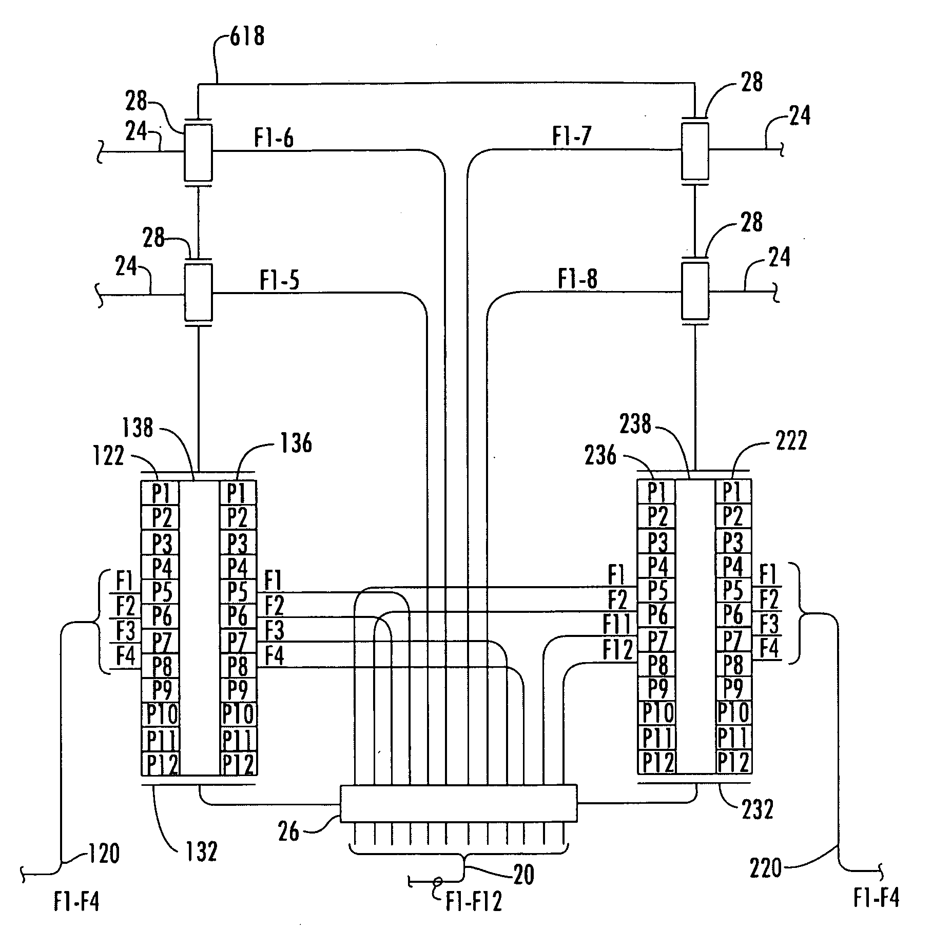
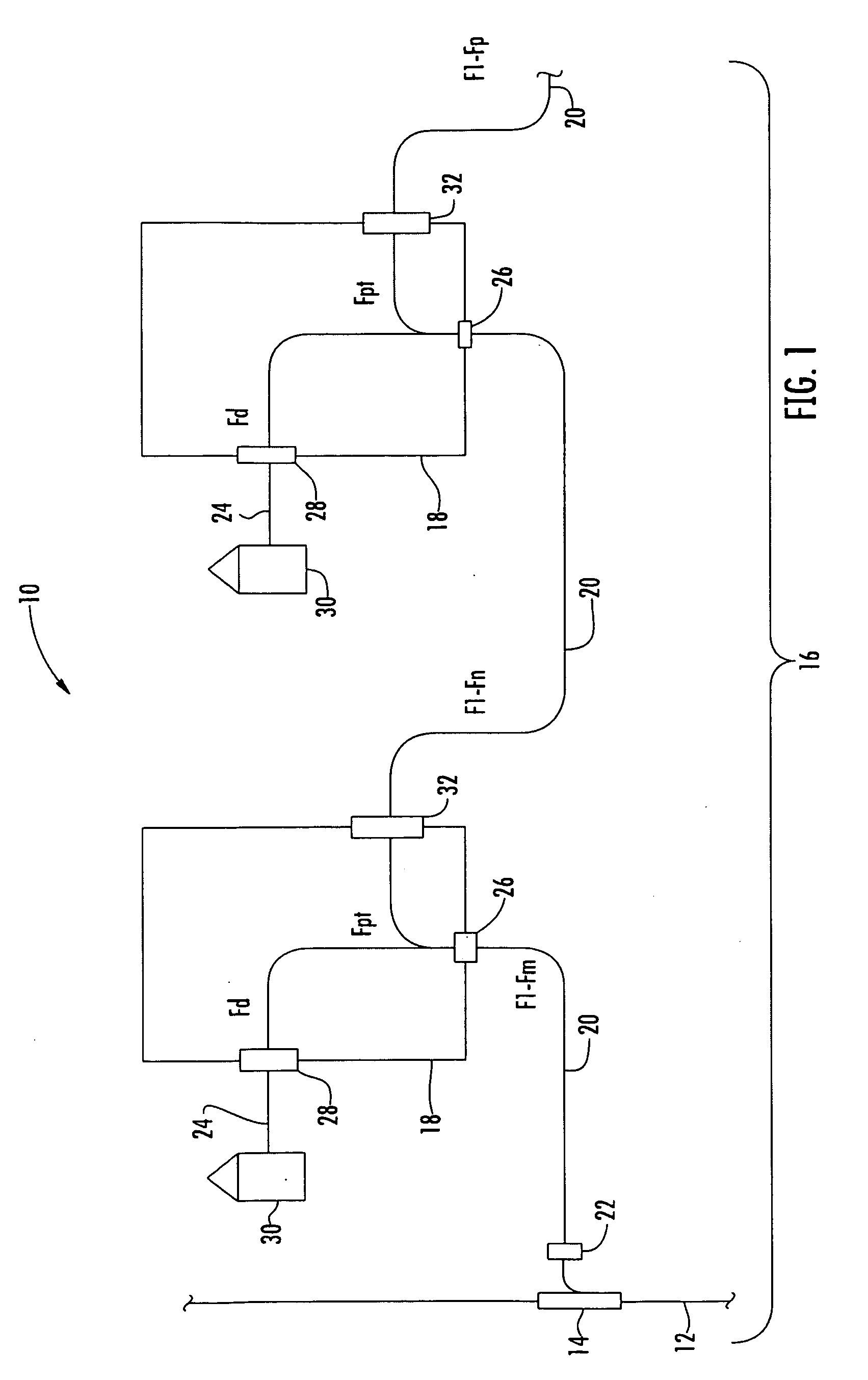
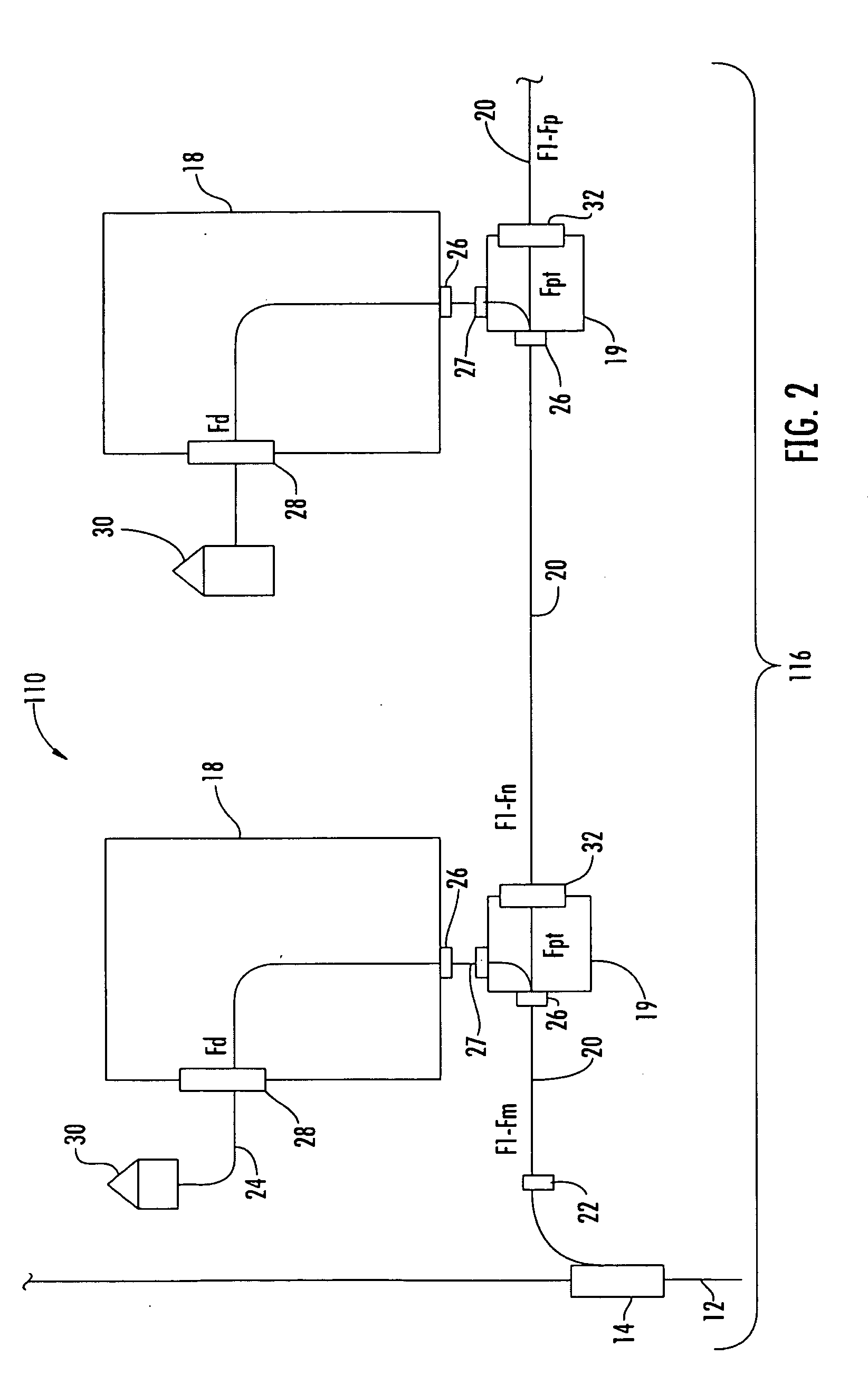
[0041]Various embodiments of a fiber optic network device having a port mapping scheme are provided. To facilitate the description of the various embodiments, an optical connection terminal may be used. It should be understood that as used herein the term optical connection termi...


PUM


Abstract

A shelf for a fiber optic network device is disclosed. The shelf comprises a platform having a top side and a bottom side. The platform is adapted to removably affix to a base of an optical connection terminal having a port disposed through the base such that the platform positions above the port. The shelf includes an access opening extending through the platform from the top side to the bottom side. The access opening provides access to the port from the top side. A transition area extends from the access opening. The transition area is adapted for routing optical fibers disposed in the optical connection terminal between a space under the platform and the top side. A component area is located on the top side, and adapted for mounting a component. At least one of the optical fibers disposed in the optical connection terminal extends from the component.

Description

CROSS-REFERENCE TO RELATED APPLICATIONS[0001]This application claims the benefit of priority to U.S. Provisional Application No. 61 / 105,306, filed on Oct. 14, 2008, the contents of which are relied upon and incorporated herein by reference in its entirety.[0002]This application is related to co-pending U.S. patent application Ser. No. ______, entitled “OPTICAL CONNECTION TERMINAL HAVING PORT MAPPING SCHEME,” which is incorporated herein by reference in its entirety.[0003]This application is related to co-pending U.S. patent application Ser. No. ______, entitled “FIBER OPTIC NETWORK ARCHITECTURE HAVING OPTICAL CONNECTION TERMINALS IN SERIES ARRANGEMENT,” which is incorporated herein by reference in its entirety.[0004]This application is related to co-pending U.S. patent application Ser. No. ______, entitled “MULTI-LEVEL DISTRIBUTED FIBER OPTIC ARCHITECTURES,” which is incorporated herein by reference in its entirety.[0005]This application is related to co-pending U.S. patent applicat...

Claims


Application Information

Patent Timeline
IPC IPC(8): G02B7/00H04L49/111
CPCG02B6/4453G02B6/4452G02B6/4472G02B6/4475
Inventor CONNER, MARK E.SCHNICK, GARY B.
Owner CORNING CABLE SYST LLC
Why Eureka
Try Eureka