Heat exchanger for a boiler

Active Publication Date: 2010-04-29
UNIVERSITY OF CALABRIA
View PDF12 Cites 7 Cited by
  • Summary
  • Abstract
  • Description
  • Claims
  • Application Information

AI Technical Summary

Benefits of technology

[0004]The aim of the invention is to prov

Problems solved by technology

The described heat exchangers are very widesprea

Method used


Image

  • Heat exchanger for a boiler
  • Heat exchanger for a boiler
  • Heat exchanger for a boiler

Examples


Example

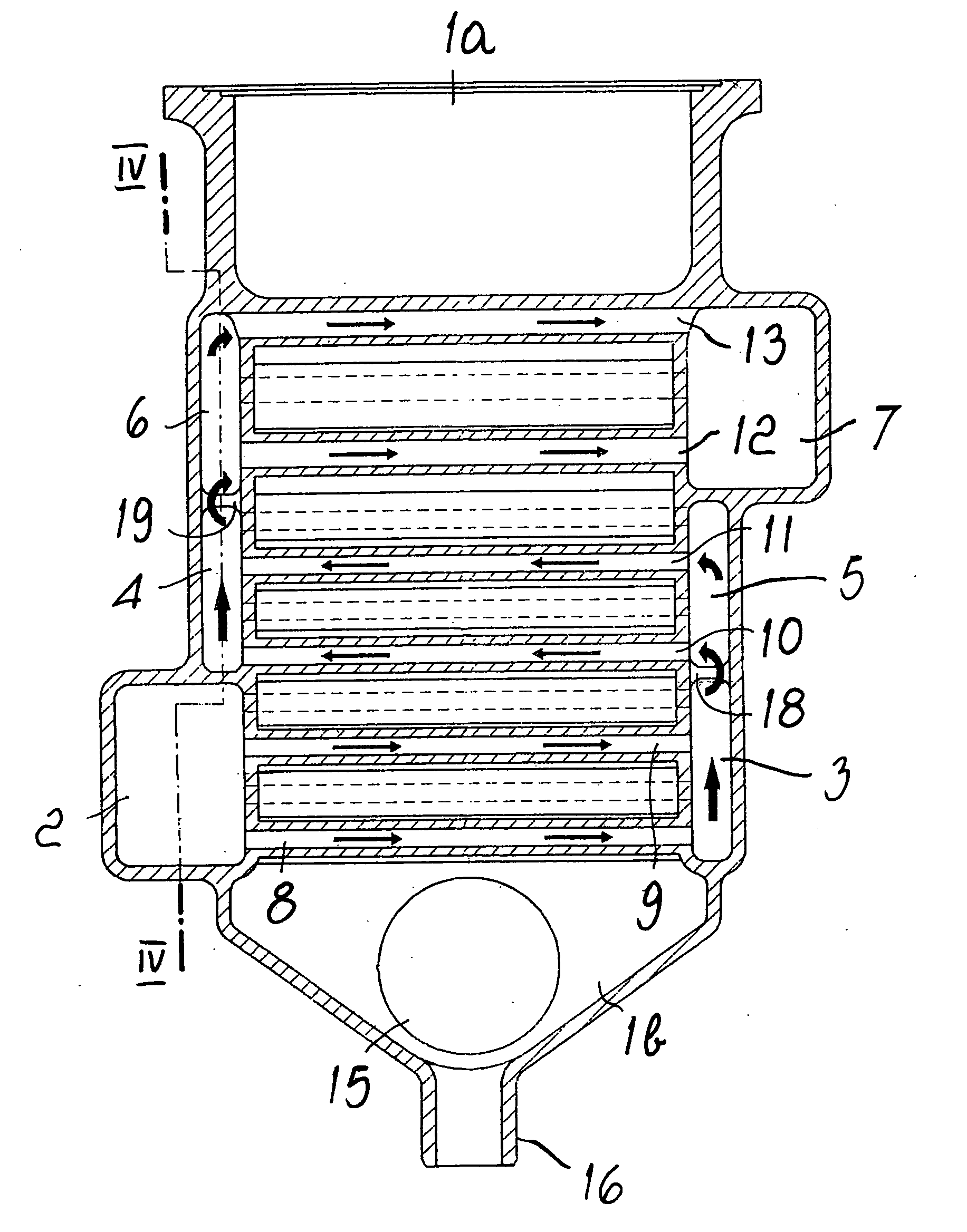
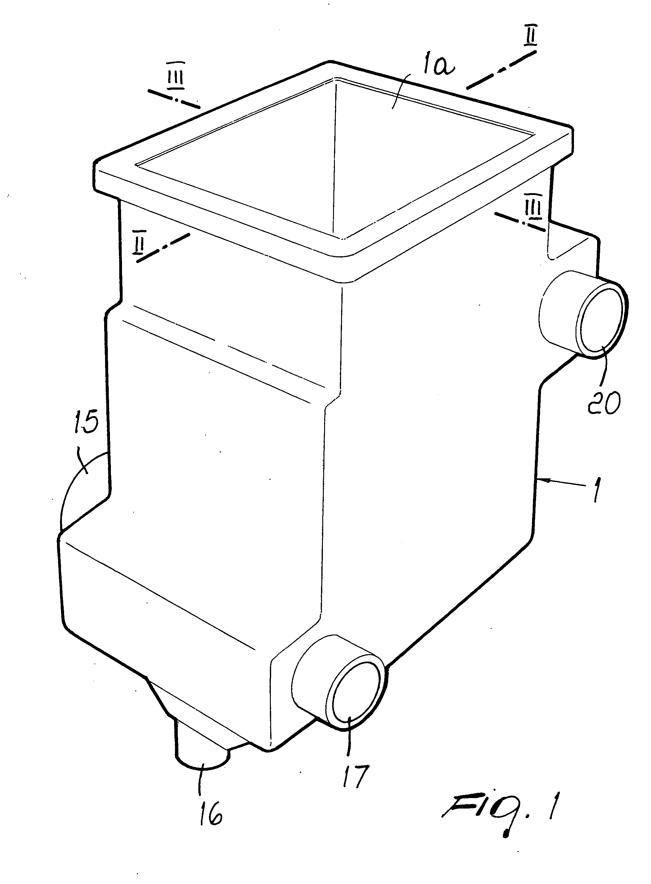
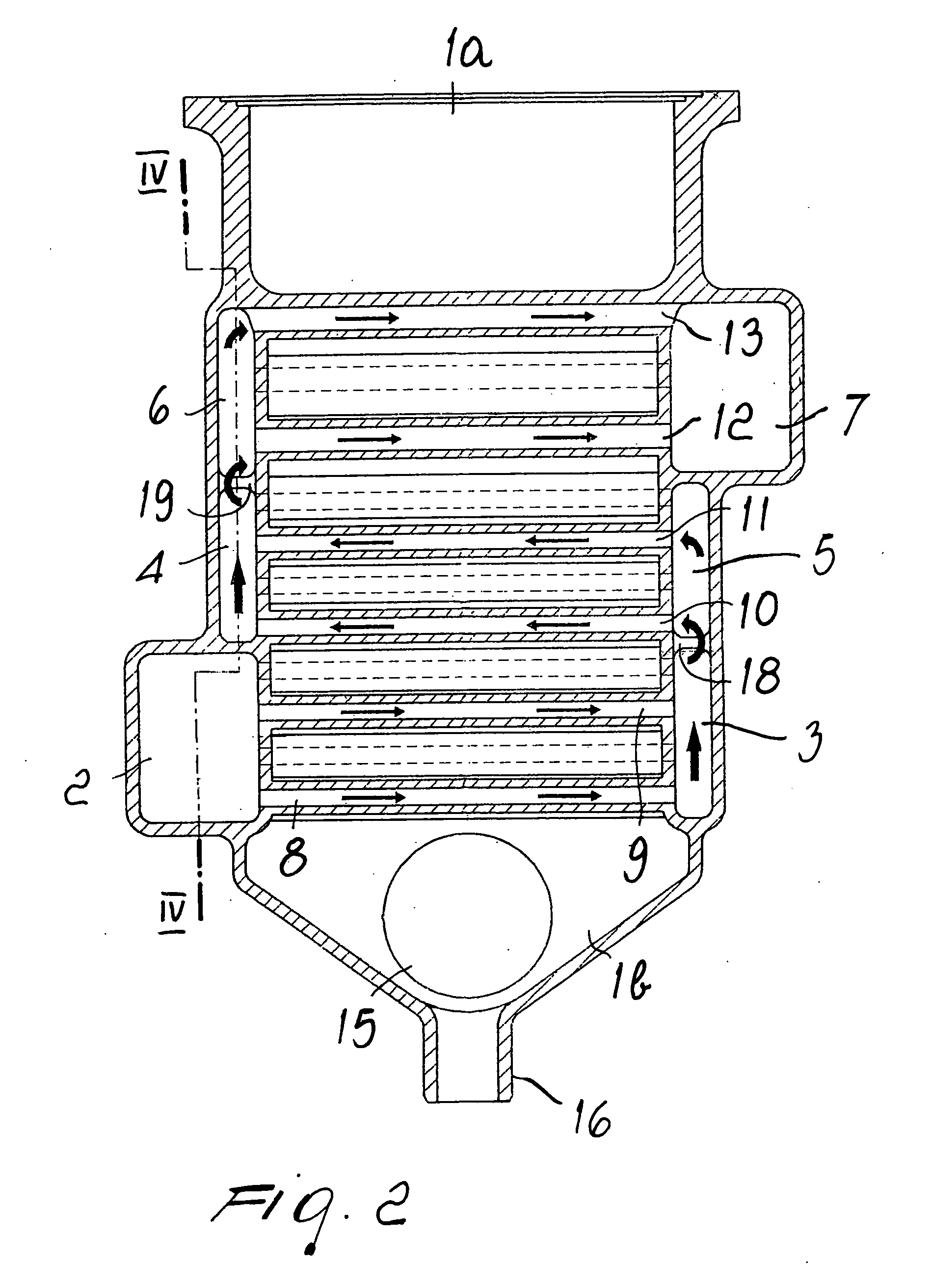
[0011]With reference to the figures, the reference numeral 1 generally designates a heat exchanger according to the invention, adopted in a gas-fired condensing boiler, which comprises, within a monolithic structure, at least one and preferably three pairs of mutually opposite manifolds designed to contain the fluid to be heated, assumingly water: the first pair is formed by manifolds 2 and 3, the second pair is formed by manifolds 4 and 5, and the third pair is formed by manifolds 6 and 7.

[0012]Such manifolds are connected by perforated pins 8 and 9 for the first pair, 10 and 11 for the second pair, 12 and 13 for the third pair, and said perforated pins are inserted within a portion of space 14 designed to convey the products of the combustion generated in a burner, not shown in the figure, which is arranged at the upper edge of a head 1a designed for flame development, to a bottom 1b provided with a duct 15 for evacuation to the stack and with a connector 16 for the discharge of c...


PUM


Abstract

A heat exchanger for a boiler, comprising, within a monolithic structure, at least one pair of mutually opposite manifolds connected by perforated pins inserted within a portion of space which is delimited by the structure and is designed to convey the products of combustion, the manifolds being adapted to provide the circulation of the fluid to be heated between an inlet connector and an outlet connector.

Description

BACKGROUND OF THE INVENTION[0001]Heat exchangers are known which are adopted in boilers designed to heat a fluid, very commonly constituted by water or diathermic oil, which comprise, within a monolithic structure often made of aluminum, two opposite plates which have a variously shaped interspace for the conveyance of the fluid to be heated and are provided with pins which are inserted in a portion of space which is designed to convey the products of combustion, so as to receive heat which is transmitted to said fluid by means of the base of said pins.[0002]In the particular case in which such exchangers are adopted in gas-fired condensing boilers, they have a burner which is located at the upper head, and the products of combustion are conveyed into a portion of space which extends from said head to the bottom of the exchanger, where there is a duct for evacuation to the stack.[0003]The described heat exchangers are very widespread but have some disadvantageous characteristics. Fo...

Claims


Application Information

Patent Timeline
IPC IPC(8): F24H9/00
CPCF24H1/40F24H8/00F24H9/0026F28F1/04F28F2250/02F28F7/02F28F13/06Y02B30/102F28F2215/04F28F1/16Y02B30/00F28D7/1623
Inventor MORINI, MARIO
Owner UNIVERSITY OF CALABRIA
Why Eureka
Try Eureka