Charge air cooler

Pending Publication Date: 2022-01-27
VALEO AUTOSYSTY
View PDF0 Cites 0 Cited by
  • Summary
  • Abstract
  • Description
  • Claims
  • Application Information

AI Technical Summary

Benefits of technology

[0023]In various embodiments of presented invention, conduits are situated between the manifolds of the first heat exchange section and the manifolds of the second heat exchange section. Owning to the fact that the first coolant conduits and the second coolant conduits are distanced within their stacks, heat exchange between the coolant and the air is improved.
[0024]According to an embodiment o

Problems solved by technology

Pressurizing the air leads to substantial increase of its temperature.
Delivering charge air from turbocharger and/or supercharger without cooling it may significantly rise engine's operating

Method used


Image

  • Charge air cooler
  • Charge air cooler
  • Charge air cooler

Examples


Example

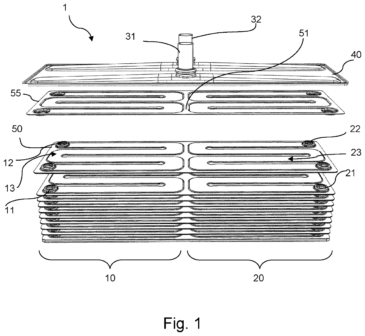
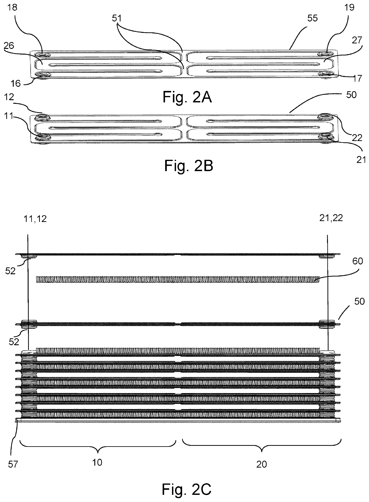
[0032]Embodiments of the invention comprise a water charge air cooler 1 with two separate coolant circulation paths further called sections. Providing more than one path of circulation for the coolant increases efficiency of water charge air cooler, as the heat exchange is facilitated. Moreover, distribution of fluid (coolant) presented in embodiments significantly decreases pressure loses (referred to as the “pressure drop”) measured on the outlet of the charge air cooler.

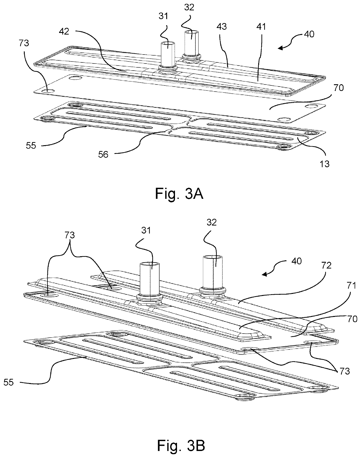
[0033]FIG. 1 shows a charge air cooler 1 in which the coolant enters through coolant inlet 31. Stream of coolant is then guided by a distribution assembly 40 to the sides of the cooler. The distribution assembly 40 is attached (e.g. brazed) a flat plate 70 and a terminal plate assembly 55. The coolant is directed into a first heat exchange section 10 and a second heat exchange section 20. In this example, heat exchange sections 10 and 20 are situated parallel to each other, thereby providing even coolant distribut...


PUM


Abstract

A charge air cooler comprising: a first heat exchange section comprising a first inlet manifold and a first outlet manifold connected fluidically by a plurality of stacked first coolant conduits; a second heat exchange section comprising a second inlet manifold and a second outlet manifold connected fluidically by a plurality of stacked second coolant conduits; a coolant inlet connected fluidically with the first inlet manifold and the second inlet manifold; a coolant outlet connected fluidically with the first outlet manifold and the second outlet manifold; wherein the first coolant conduits and the second coolant conduits are distanced within their stacks so that heat exchange between the coolant and the air is enabled, and are both situated between the manifolds of the first heat exchange section and the manifolds of the second heat exchange section.

Description

FIELD OF THE INVENTION[0001]The invention relates to a charge air cooler, in particular to a water charge air cooler for a motor vehicle.BACKGROUND OF THE INVENTION[0002]As commonly known, power produced from naturally aspirated engines depends mostly on its efficiency and displacement. At the sea level, naturally aspirated engine is able to inhale only such amount of air, which is delivered by atmospheric force i.e. 1 bar. Moreover, atmospheric pressure decreases with elevation. However, conventional engines can be easily upgraded in order to increase its performance, thermal efficiency and fuel economy.[0003]To overcome the limitations of an atmospheric pressure, air is pressurized (herein referred to as the “charge air”) by mechanical or electric compressors, known as superchargers or turbochargers. In the forced induction engines, power output becomes a function of how much air is delivered to the cylinders. Most commonly used methods to put these compressors into action recaptu...

Claims


Application Information

Patent Timeline
IPC IPC(8): F28D9/00
CPCF28D9/0062F28D9/0056F28D9/0093F28D2021/0082Y02T10/12
Inventor SZOSTEK, DAWIDROMANSKI, GRZEGORZBUREK, DARIUSZKANIA, LUKASZ
Owner VALEO AUTOSYSTY
Why Eureka
Try Eureka