
Method and apparatus for digitally evaluating insertion quality of customized orthodontic arch wire

a technology of orthodontic arch wires and digital evaluation, applied in the field of computerized techniques for orthodontic treatment planning for human patients, can solve problems such as conflict or collision, optimization steps that fail, and conflict recording

Inactive Publication Date: 2010-04-29
ORAMETRIX
View PDF4 Cites 17 Cited by
  • Summary
  • Abstract
  • Description
  • Claims
  • Application Information

AI Technical Summary

Benefits of technology

"The patent describes a method for digitally checking the insertion quality of a custom arch wire designed to move teeth in orthodontic treatment. The method involves simulating the insertion of the wire into virtual brackets on the teeth and evaluating if there are any conflicts or collisions between the wire and the brackets. The method can be used to design the arch wire and select the starting point for the treatment. The results of the wire insertion process can be displayed to the user in real-time. The method helps to ensure the proper insertion of the arch wire and improves the efficiency of the treatment process."

Problems solved by technology

Conflicts are undesirable since they cause the arch wire to loose its effectiveness in terms of moving the patient's teeth from, say malocclusion state to the target state.
It may be recalled that a conflict or a collision is created when a portion of a bent segment gets unavoidably inserted into a bracket slot during the arch wire insertion process.
On the other hand, if the conflict persists in spite of the optimization, then the optimization step has failed, and the conflict is recorded at the neighbor.

Method used


Image

  • Method and apparatus for digitally evaluating insertion quality of customized orthodontic arch wire
  • Method and apparatus for digitally evaluating insertion quality of customized orthodontic arch wire
  • Method and apparatus for digitally evaluating insertion quality of customized orthodontic arch wire

Examples


Embodiment Construction

Overview

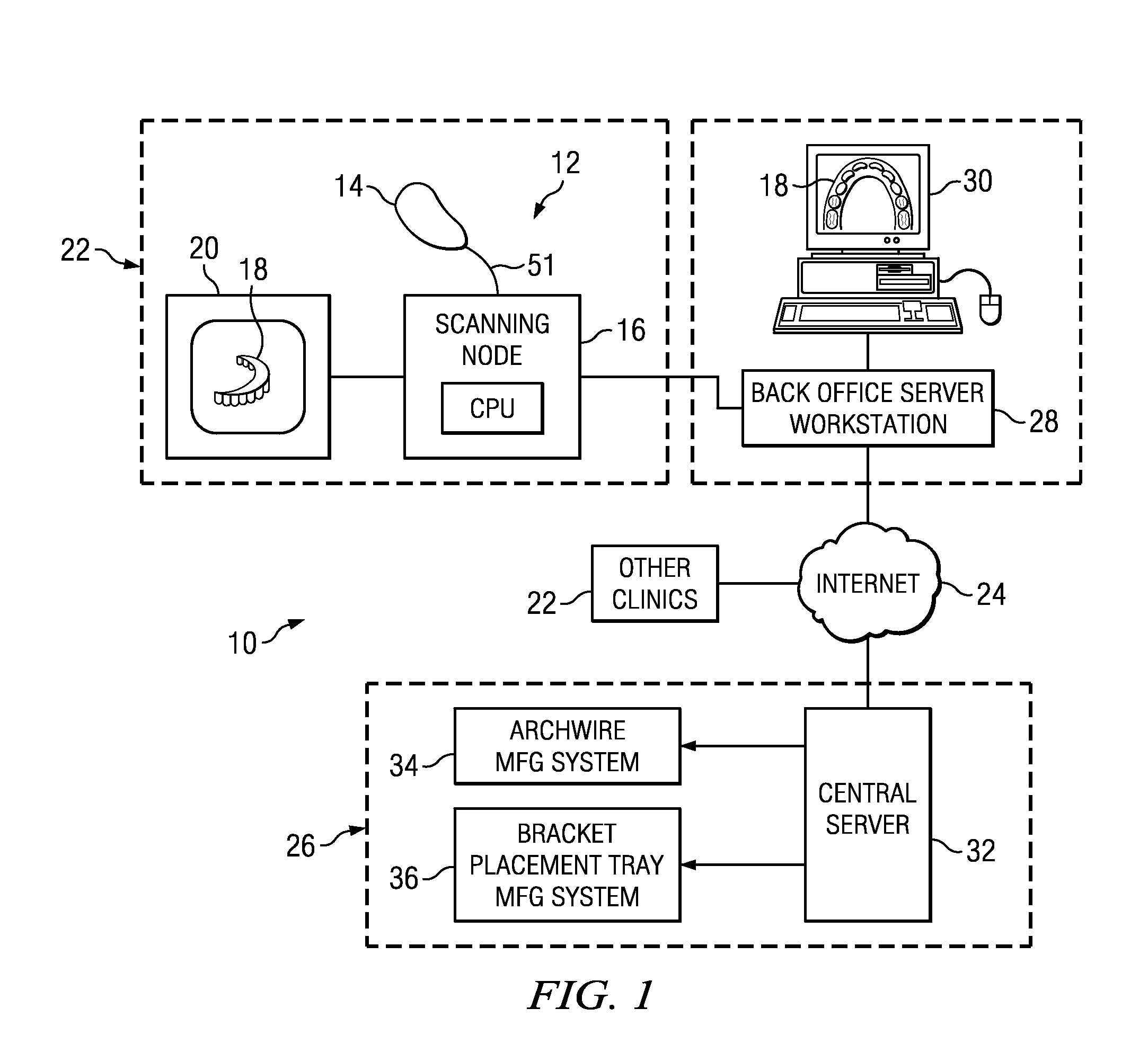
[0080]FIG. 1 is an illustration of an orthodontic care system 10 incorporating a scanner system 12. The scanner system 12 includes a hand-held scanner 14 that is used by the orthodontist or his assistant to acquire three-dimensional information of the dentition and associated anatomical structures of a patient. The images are processed in a scanning node or workstation 16 having a central processing unit, such as a general-purpose computer. The scanning node 16, either alone or in combination with a back-office server 28, generates a three-dimensional computer model 18 of the dentition and provides the orthodontist with a base of information for diagnosis, planning treatment, and monitoring care for the patient. The model 18 is displayed to the user on a monitor 20 connected to the scanning node 16.

[0081]As noted above, the scanner system 12 is optimized for in-vivo scanning of teeth, or alternatively, scanning a plaster model of the teeth and / or an impression of the teeth.

[...


PUM


Abstract

A method and apparatus is provided for digitally checking the insertion quality of a target customized virtual arch wire designed during treatment planning prior to actually manufacturing the target arch wire. The method includes the steps of digitally simulating the insertion of the customized target virtual arch wire into the virtual brackets placed up on virtual teeth of a patient in an initial state of interest for checking if the arch wire could be inserted into the virtual brackets without conflicts or collisions. The initial state may be a malocclusion state or any intermediate treatment state of the patient. In the event the target virtual arch wire would cause conflicts, then the simulation optimizes the arch wire design in an attempt to eliminate the conflicts. In another aspect, a method is provided for selecting the recommended starting point for inserting the customized arch wire in the brackets placed on the dentition of the patient in the initial state.

Description

CROSS-REFERENCE TO RELATED APPLICATIONS[0001]This application is a divisional application of the U.S. patent application Ser. No. 11 / 233,946, filed Sep. 23, 2005, pending, and related to another divisional application of U.S. patent application Ser. No. 11 / 233,946, Attorney Docket No. ORA-04-016B, filed concurrently with the instant application. The entire contents of each of the above-referenced patent applications are incorporated by reference herein.BACKGROUND OF THE INVENTION[0002]A. Field of the Invention[0003]This invention relates to the field of computerized techniques for orthodontic treatment planning for human patients. More particularly, the invention is directed to a method and apparatus for checking if a target virtual orthodontic arch wire can be inserted into virtual brackets placed on the virtual malocclusion dentition of a patient without conflicts. Additionally, the invention discloses a process whereby the target orthodontic virtual arch wire can be redesigned in...

Claims


Application Information

Patent Timeline
Patent Type & Authority Applications(United States)
IPC IPC(8): G06F17/50
CPCA61C7/00A61C2007/004A61C13/0004A61C7/002
Inventor SPORBERT, PEERKOUZIAN, DIMITIJIMGRUND, HANSMAETZEL, STEPHAN
Owner ORAMETRIX
Learn More