
Locking differential with shear pin/spring assembly

a technology of shear pins and springs, applied in the direction of manufacturing tools, transportation and packaging, etc., can solve the problem of one or more shear pins and/or springs falling out of their respective bores

Active Publication Date: 2010-05-06
RING & PINION SERVICE
View PDF43 Cites 23 Cited by
  • Summary
  • Abstract
  • Description
  • Claims
  • Application Information

AI Technical Summary

Benefits of technology

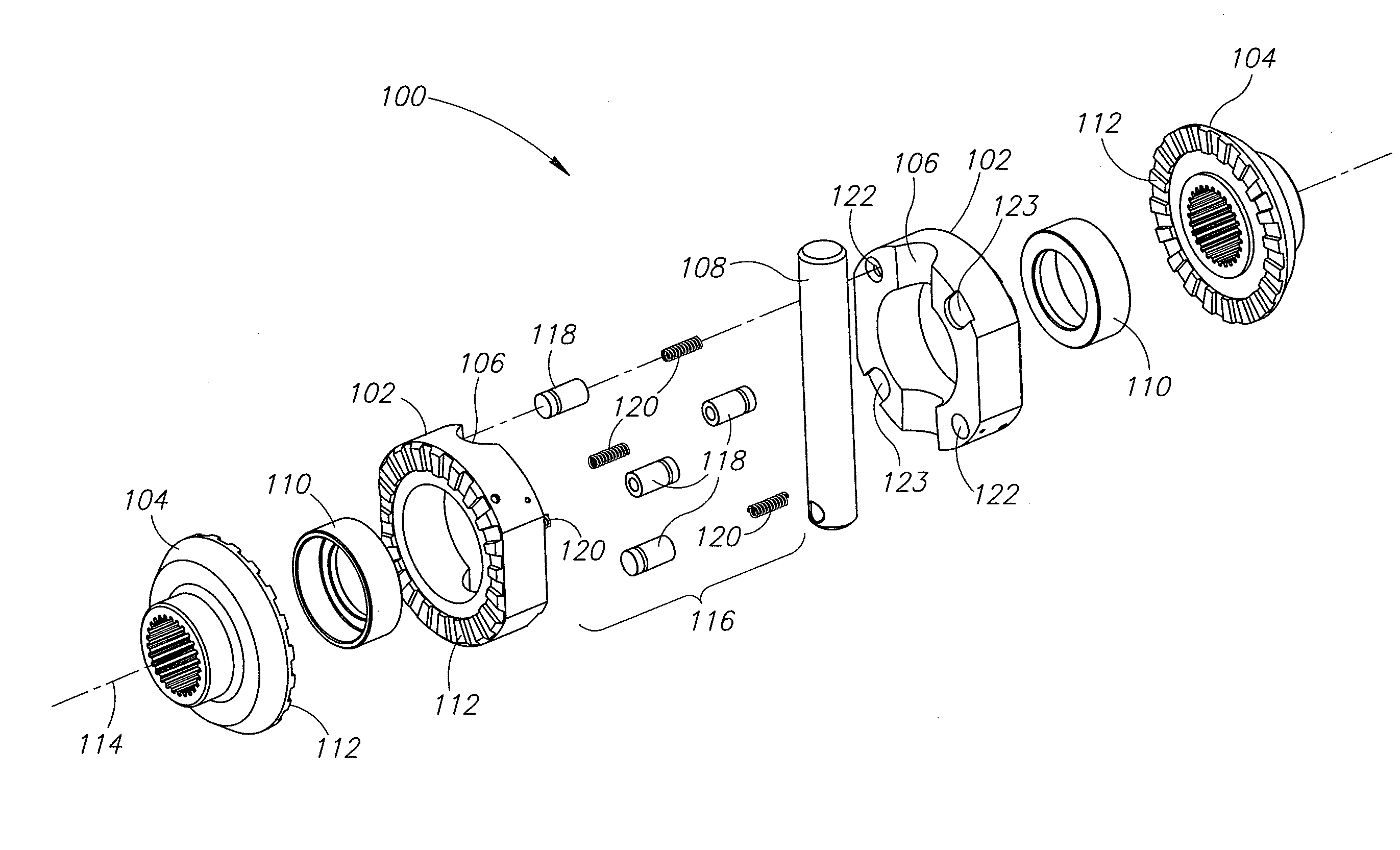
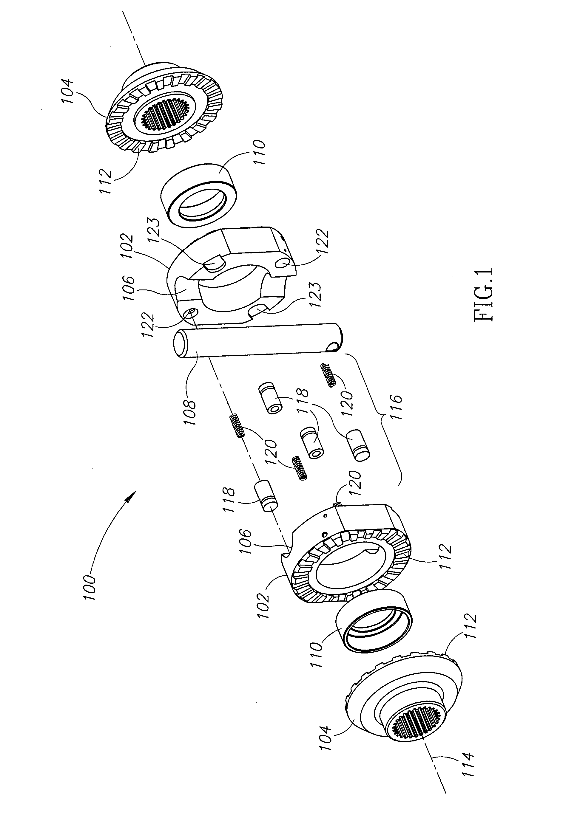
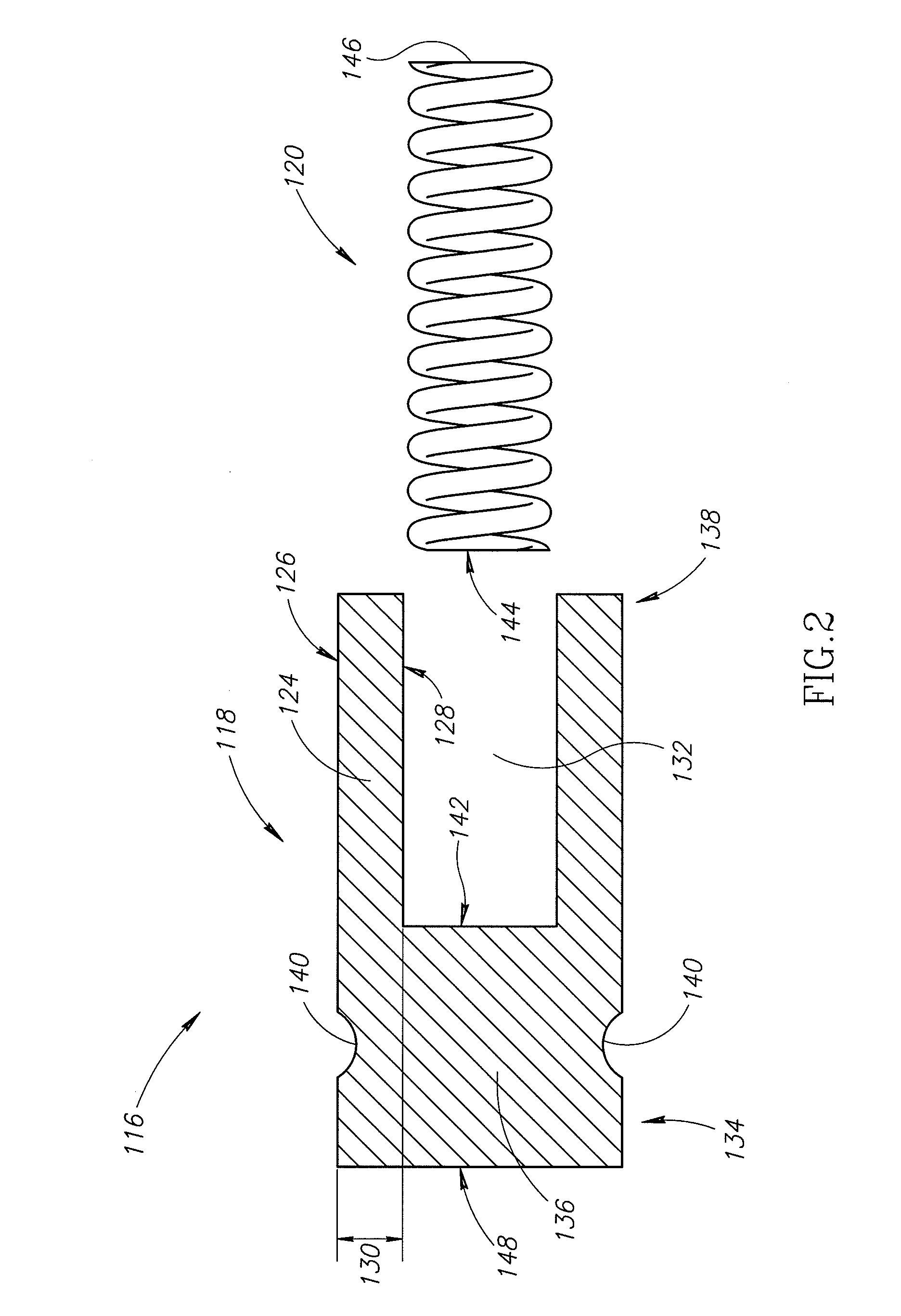
[0007]The present invention is generally related to a clutch assembly for a locking differential. The clutch assembly includes driving clutch members engaged with driven clutch members in a preloaded configuration to provide a minimum amount of preload there between during low torque conditions. The driving clutch members are biased relative to each other with shear pin / spring assemblies located within bores of the driving clutch members. During assembly of the clutch assembly, the shear pin / spring assemblies may be positively locked down within the bores with a removable tool. In one embodiment, the removable tool is inserted into a small opening extending through the driving clutch member and the tool engages an annular groove on a shear pin of the shear pin / spring assembly. Further, the clutch assembly may include driving clutch members having drainage openings that may help prevent hydraulic lock during operation or assembly of the locking differential.

Problems solved by technology

Nevertheless, the assembly process of inserting the shear pin and spring assemblies into the bores of the driving clutch members and establishing the minimum amount of preload has a number of drawbacks.
By way of example, holding the shear pins and springs in the bores of one driving clutch member while attempting to engage the corresponding driving clutch member may result in one or more of the shear pins and / or springs falling out of its respective bore.

Method used


Image

  • Locking differential with shear pin/spring assembly
  • Locking differential with shear pin/spring assembly
  • Locking differential with shear pin/spring assembly

Examples


Embodiment Construction

[0024]In the following description, certain specific details are set forth in order to provide a thorough understanding of various embodiments of the invention. However, one skilled in the art will understand that the invention may be practiced without these details or with various combinations of these details. In other instances, well-known structures and methods associated with differential systems, driving and output mechanisms for the differential systems, clutch assemblies for differential systems, and sub-assemblies located within a housing or case of the differential system, and methods of assembling, operating and using the same may not be shown or described in detail to avoid unnecessarily obscuring descriptions of the embodiments of the invention.

[0025]FIG. 1 shows an embodiment of the present invention that takes the form of a clutch assembly 100 for a locking differential having driving clutch members 102, which may otherwise be referred to as drivers, engaged with driv...


PUM

PropertyMeasurementUnit
compression forceaaaaaaaaaa
spring compression forceaaaaaaaaaa
pressureaaaaaaaaaa

Abstract

A clutch assembly for a locking differential includes driving clutch members engaged with driven clutch members in a preloaded configuration to provide a minimum amount of preload there between during low torque conditions. The driving clutch members are biased relative to each other with shear pin / spring assemblies located within bores of the driving clutch members. During assembly of the clutch assembly, the shear pin / spring assemblies may be positively locked down within the bores with a removable tool. In one embodiment, the removable tool is inserted into a small opening extending through the driving clutch member and the tool engages an annular groove on a shear pin of the shear pin / spring assembly. Further, the clutch assembly may include driving clutch members having drainage openings that may help prevent hydraulic lock during operation of the locking differential.

Description

FIELD OF THE INVENTION[0001]This invention relates generally to a locking differential system having a lockable shear pin / spring assembly, and more specifically to a shear pin / spring assembly that may be positively locked during assembly using a suitable tool.BACKGROUND OF THE INVENTION[0002]Differentials for automotive-type applications are used in many front or rear axles to transmit the power from the engine to the driven wheels of the vehicle. Conventional differentials permits a vehicle to turn corners with one wheel rolling faster than the other and generally include two side gears coupled to the output or driven shafts, which in turn are coupled to the respective left and right wheels of the vehicle. The differential case generally includes a ring gear driven by a pinion gear coupled to an end of the vehicle drive shaft driven by the engine. Side gears are located within and coupled to the differential case while typically being splined or otherwise coupled to the respective ...

Claims


Application Information

Patent Timeline
Patent Type & Authority Applications(United States)
IPC IPC(8): F16H48/20B23P11/00F16H48/12
CPCF16H48/142F16H48/24Y10T29/49863Y10T29/49959Y10T74/19005Y10T29/4984
Inventor HAUGEBERG, BRYAN
Owner RING & PINION SERVICE
Learn More