Firearm mounting mechanism

Active Publication Date: 2010-05-20
ABRAMS AIRBORNE
View PDF4 Cites 46 Cited by
  • Summary
  • Abstract
  • Description
  • Claims
  • Application Information

AI Technical Summary

Benefits of technology

[0013]This interference with the flashlight in the through bore, stops the travel of the floating block and allows the mount to adju

Problems solved by technology

These mounts, which most often are designed to hold a commercial flashlight, or similar tube shaped device, are often bulky, designed for only one specific accessory, and tedious to adjust, install and remove.
The attachment to either the firearm or flashlight is semi-perma

Method used


Image

  • Firearm mounting mechanism
  • Firearm mounting mechanism
  • Firearm mounting mechanism

Examples


Example

DRAWINGS IN DETAIL

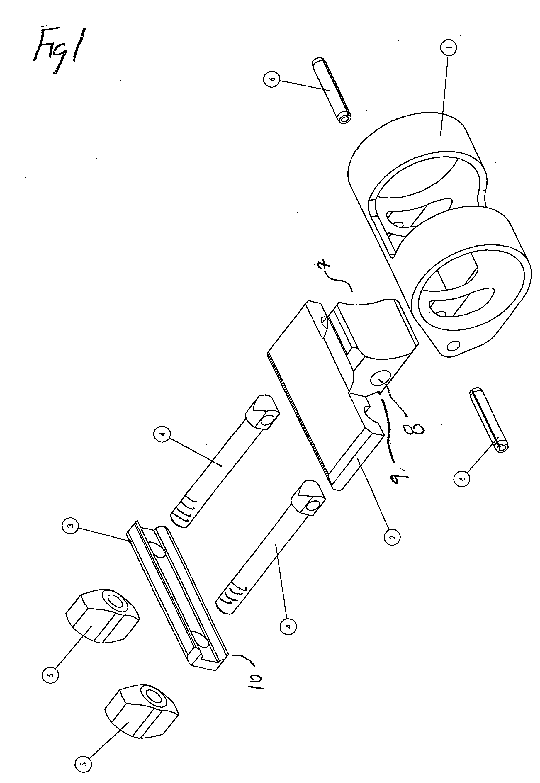
[0022]FIG. 1 is a disassembled view of the preferred embodiment of the invention.

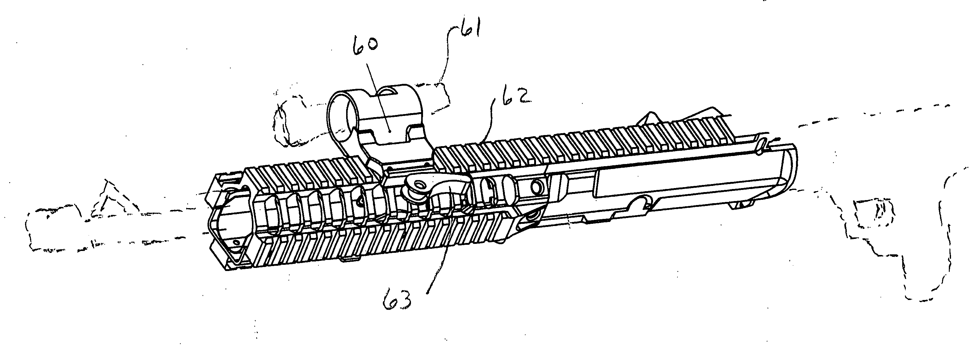
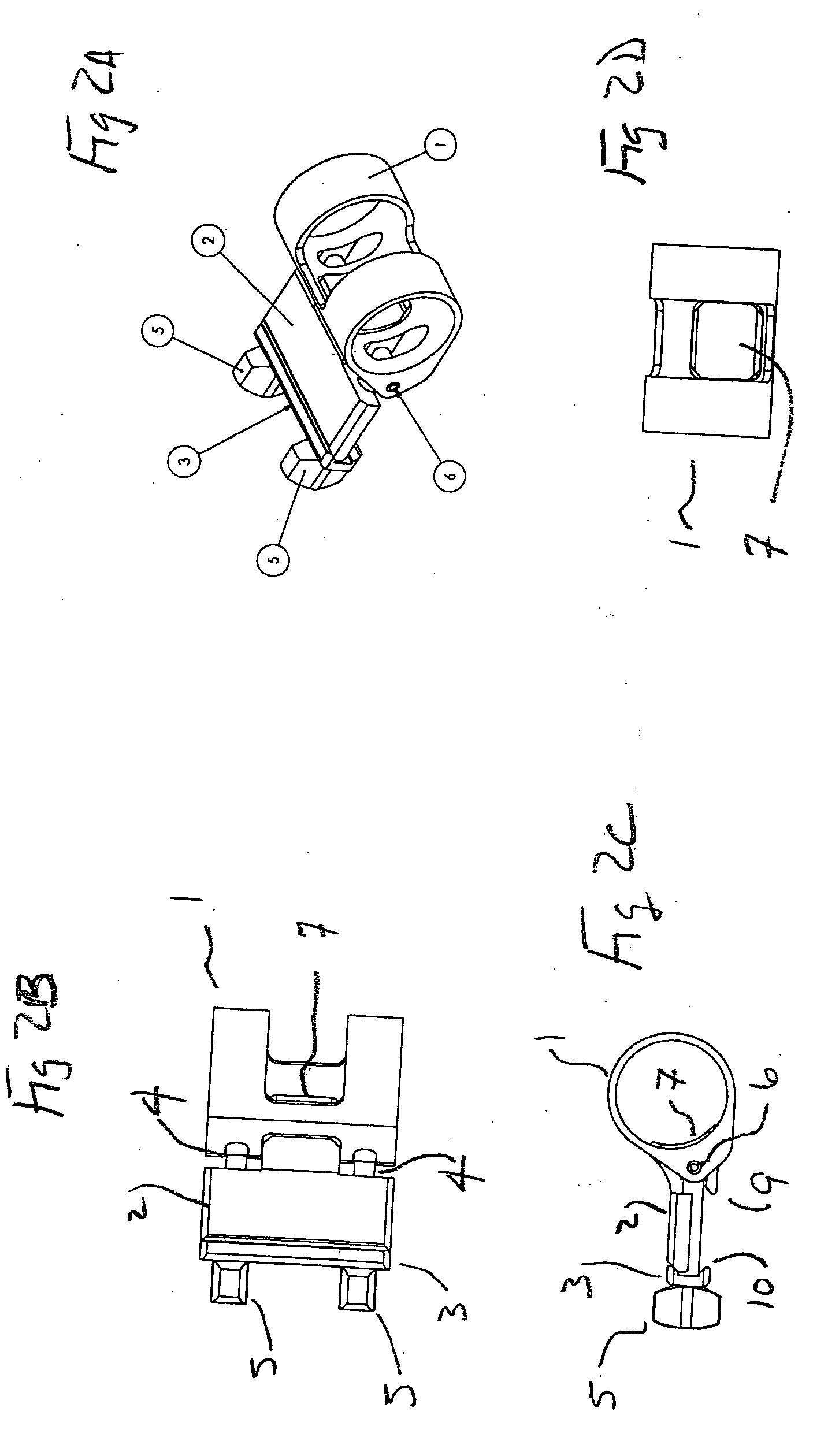
[0023]Holder 1 is configured to encircle an accessory for a firearm. This accessory, in this illustration, has a circular cross-section (such as a flashlight or a sighting laser). Secured to holder 1 are two guide members 4 which are secured to holder 1 via pins 6.

[0024]Pins 6 fit snugly into holder 1 and one end of guide members 4. Further, pins 6, in this embodiment of the invention, loosely engage tooth member 7 via hole 8. Hole 8 has a much greater diameter than the diameter of pin 6 and is used to maintain tooth 7 within holder 6; but, at the same time, pins 6 allow movement of tooth 7.

[0025]On tooth 7 is a clamping mechanism 9 which is configured to engage one side of the receiving mechanism on the firearm. Bracket 3 has two openings through which guides 4 extend. A bottom edge of bracket 3 is configured to engage a second side of the receiving mechanism.

[0026]A top side of brack...


PUM


Abstract

A combination and accessory for a firearm having a receiving mechanism such as a Picanny rail or similar mechanism. A bracket is used to secure an accessory to the firearm via the receiving mechanism. The bracket mechanism uses a holder configured to encircle a portion of the accessory and a securing bracket adapted to engage the receiving mechanism. A manually operated compression mechanism simultaneously engages the securing bracket with said receiving mechanism and the holder with said accessory for a firearm

Description

BACKGROUND OF THE INVENTION[0001]This invention relates generally to firearms and more particularly to a mounting mechanism used to secure accessory apparatus to the firearm.[0002]In recent years, there has been an increase in practice and options of temporarily attaching various ancillary devices to firearms; these devices are varied in purpose and function, but among the most popular are flashlights, light collimator and laser devices for illumination, target identification / designation and aiming.[0003]There is an increasing popularity in the firearms industry, to incorporate attachment rails for such devices; either into new firearm designs, or by way of add-on accessories. The locations and specifics of these attachment rails has become too numerous to mention, but is best typified by the attachment rails located around the forward handguard of current U.S. military and law enforcement rifles. Consequently, there are numerous types of mounts designed to attach to these rail syst...

Claims


Application Information

Patent Timeline
IPC IPC(8): F41C27/00F41G1/00
CPCF41C27/00F41G11/004F41G1/387
Inventor KINCEL, ERIC STEPHEN
Owner ABRAMS AIRBORNE
Why Eureka
Try Eureka