
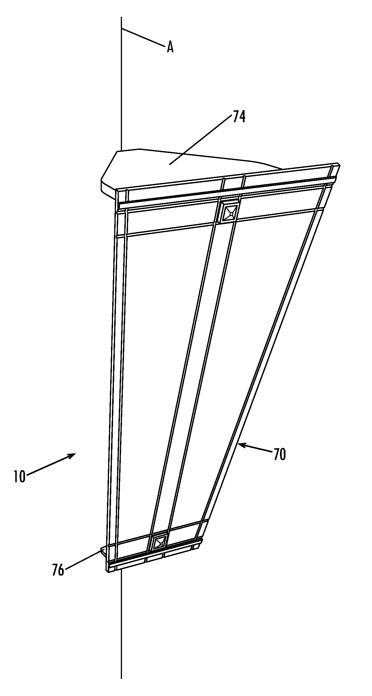
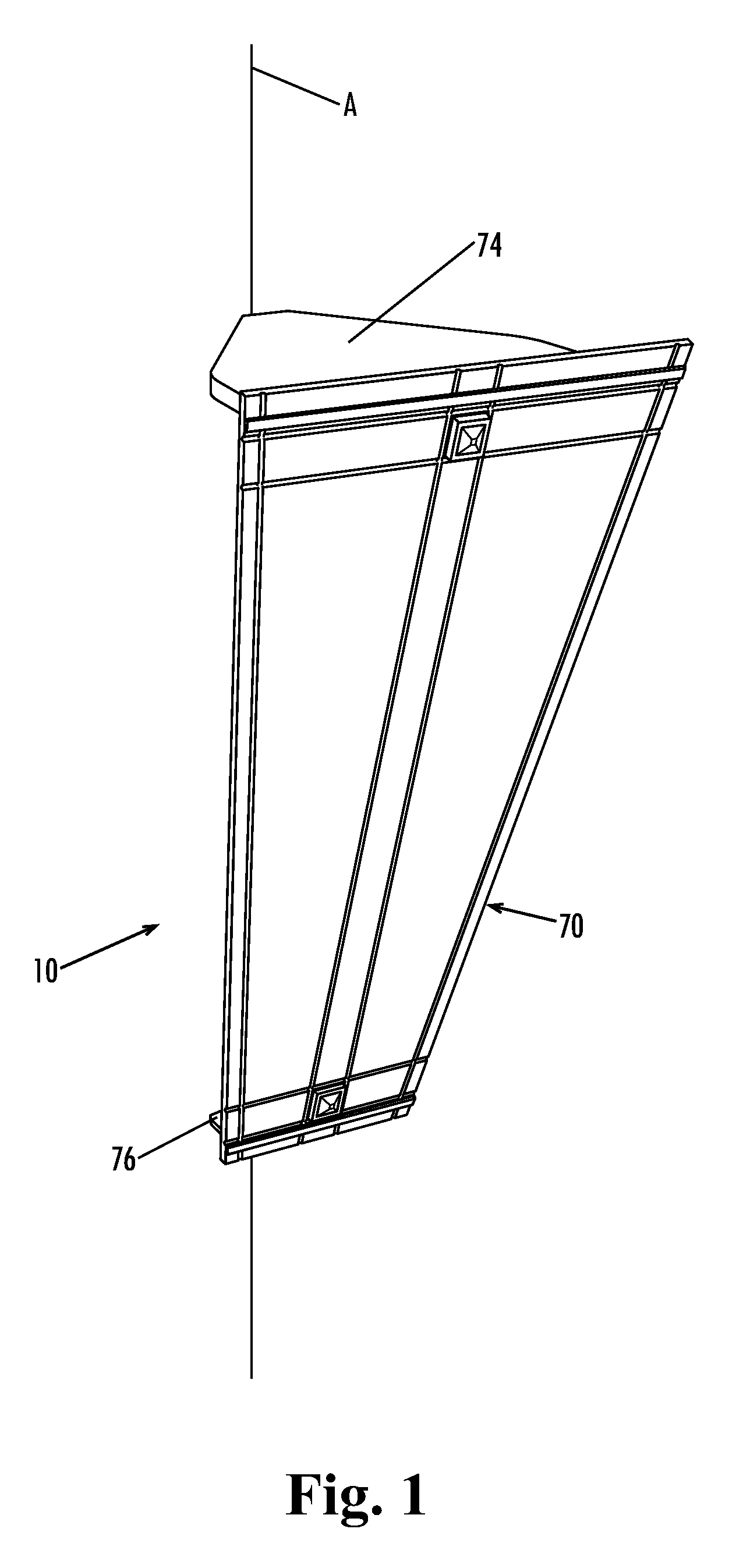
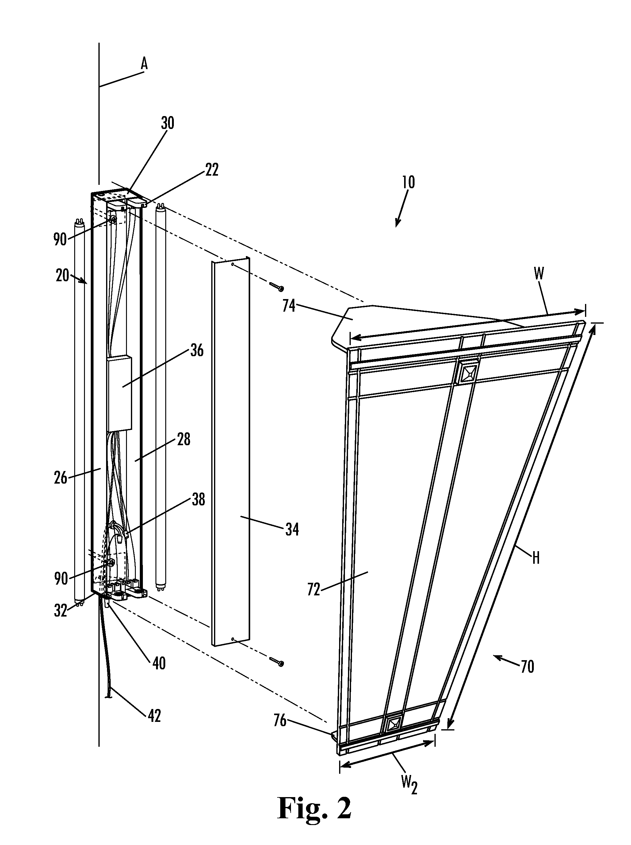
Corner mounted light fixture

a technology of light fixtures and corners, applied in the field of lighting, can solve the problems of shoddy appearance, interference with proper structural support, uneven or incorrect light distribution, etc., and achieve the effect of convenient installation and economics

Inactive Publication Date: 2010-05-27
RLR INDS
View PDF22 Cites 1 Cited by
  • Summary
  • Abstract
  • Description
  • Claims
  • Application Information

AI Technical Summary

Benefits of technology

"The present invention provides an improved corner mounted lighting fixture that is economical, easy to install, and provides proper alignment and light distribution without the need for specialized tools, training, or separate hardware. The fixture includes a base and a corner bracket that aligns with the included angle between the first and second walls. The fixture also includes a diffuser that attaches to the base and a front cover plate. The invention also includes a method of installing the fixture in a corner between first and second walls, and a line of intersection of the first and second walls defining a corner axis. The method includes mounting a fixture base along the corner axis by aligning at least one angular alignment flange extending from the fixture base within the corner, and installing at least one fastener through the fixture base and intersecting the corner axis. The technical effects of the invention include improved alignment and light distribution, economical and easy installation, and proper alignment without the need for specialized tools, training, or separate hardware."

Problems solved by technology

Inaccurate alignment during installation can result in an uneven or incorrect light distribution, present a shoddy appearance, and in some instances may interfere with proper structural support and anchoring of the fixture onto the wall.
As a result, economies of scale available for higher volume standard fixture arrangements are generally unobtainable.
Alternatively, specialized tools or mounting hardware may be required, which can also increase costs substantially.

Method used


Image

  • Corner mounted light fixture
  • Corner mounted light fixture
  • Corner mounted light fixture

Examples


Embodiment Construction

[0015]The present invention may be understood more readily by reference to the following detailed description of the invention taken in connection with the accompanying drawing figures, which form a part of this disclosure. It is to be understood that this invention is not limited to the specific devices, methods, conditions or parameters described and / or shown herein, and that the terminology used herein is for the purpose of describing particular embodiments by way of example only and is not intended to be limiting of the claimed invention. Any and all patents and other publications identified in this specification are incorporated by reference as though fully set forth herein.

[0016]Also, as used in the specification including the appended claims, the singular forms “a,”“an,” and “the” include the plural, and reference to a particular numerical value includes at least that particular value, unless the context clearly dictates otherwise. Ranges may be expressed herein as from “abou...


PUM


Abstract

A corner mounted lighting fixture having alignment features on its fixture base and on its diffuser for maintaining alignment with the corner during assembly and installation. The diffuser is positioned at an incline within the corner for improved light distribution. Attachment is along the axis of the corner for ease of installation.

Description

CROSS-REFERENCE TO RELATED APPLICATION[0001]This application is a continuation of U.S. Non-Provisional patent application Ser. No. 12 / 121,046 filed May 15, 2008, the entirety of which is hereby incorporated herein by reference for all purposes.TECHNICAL FIELD[0002]The present invention relates generally to the field of lighting, and more particularly to light fixtures.BACKGROUND OF THE INVENTION[0003]Many varieties of lighting fixtures are known, including ceiling mounted fixtures, wall mounted fixtures, floor standing lamps, table lamps, and the like. In some instances, users may wish to mount a lighting fixture in a corner between two walls. Corner mounted applications commonly require more precise alignment during installation than typical wall mounted light fixture applications. This is especially so in applications where the fixture and / or associated diffuser components are intended to closely align with the walls adjacent the corner, in fixtures that are installed at compound ...

Claims


Application Information

Patent Timeline
Patent Type & Authority Applications(United States)
IPC IPC(8): F21S8/00
CPCF21S8/037F21Y2103/00F21V21/02F21V15/01F21Y2113/00
Inventor SENKYR, KEITH A.
Owner RLR INDS
Learn More