
Sound Reduce Segmented Idler For Track-Type Vehicles

a technology of idlers and tracks, applied in mechanical equipment, transportation and packaging, hoisting equipment, etc., can solve the problems of noise generation between track chains and idler wheels, noise and vibration in earth moving and construction track-type machines, and the noise of center tread idlers can be mor

Inactive Publication Date: 2010-06-03
CATERPILLAR INC
View PDF21 Cites 41 Cited by
  • Summary
  • Abstract
  • Description
  • Claims
  • Application Information

AI Technical Summary

Benefits of technology

[0006]In another aspect of the disclosure, an idler for a track-type undercarriage including a track comprising interconnected track links and bushings associated with the track links and positioned to contact the idler is provided. The bushings may be separated from each other along the t

Problems solved by technology

A source of noise in earth moving and construction track-type machines originates from the endless track chains as they revolve around and make contact with undercarriage components of the track-type machine.
Since these components are manufactured using metal, noise and vibration is generated between the track chains and the idler wheels during operation.
Generally speaking, center tread idlers can produce more noise than standard idlers.

Method used


Image

  • Sound Reduce Segmented Idler For Track-Type Vehicles
  • Sound Reduce Segmented Idler For Track-Type Vehicles
  • Sound Reduce Segmented Idler For Track-Type Vehicles

Examples


second embodiment

[0039]Clamping plates 380 in the second embodiment may each have a clamping portion 390 that interlocks with a respective one of the side surfaces 354 of the rim members 350 to interlock the clamping plates 380 and rim members 350. The clamping portion 390 may include a second transition surface 392 extending radially and axially inward at an angle with respect to the axis of rotation 119. As depicted in FIG. 12, angle 393 may be equal to or less than 65 degrees with respect to a line parallel to the axis of rotation 119. In one configuration, the second transition surface 392 may extend inward at an angle between about 25 and about 65 degrees. However, it is envisioned that the second transition surface 392 can extend inward at an angle between 0 and 90 degrees without departing from the scope of the disclosure. A second locking surface 396 may extend radially inward and axially outward from the second transition surface 392. As depicted in FIG. 12, the second locking surface 396 e...

third embodiment

[0043]FIG. 13 illustrates the idler 414. The side surfaces 454 may include a transition surface 464 extending radially and axially inward from a shoulder 462. As depicted in FIG. 13, angle 465 is shown at an angle of about 55 degrees with respect to a line parallel to the axis of rotation 119. In one configuration, the transition surface 464 may extend inward at an angle ranging between 0 degrees and 55 degrees. A locking surface 470 may extend axially outward from the transition surface 464, generally parallel to the axis of rotation 119. Together, the transition surface 464 and the locking surface 470 form a recess 468. A side portion 472 may extend radially inward from the locking surface 470, generally perpendicular to the axis of rotation 119. An inner surface 458 may extend axially inward from the side portion 472. Together, the locking surface 470, side portion 472, and inner surface 458 form a protrusion 474. The protrusion and recess 468 may be individually or collectively ...


PUM


Abstract

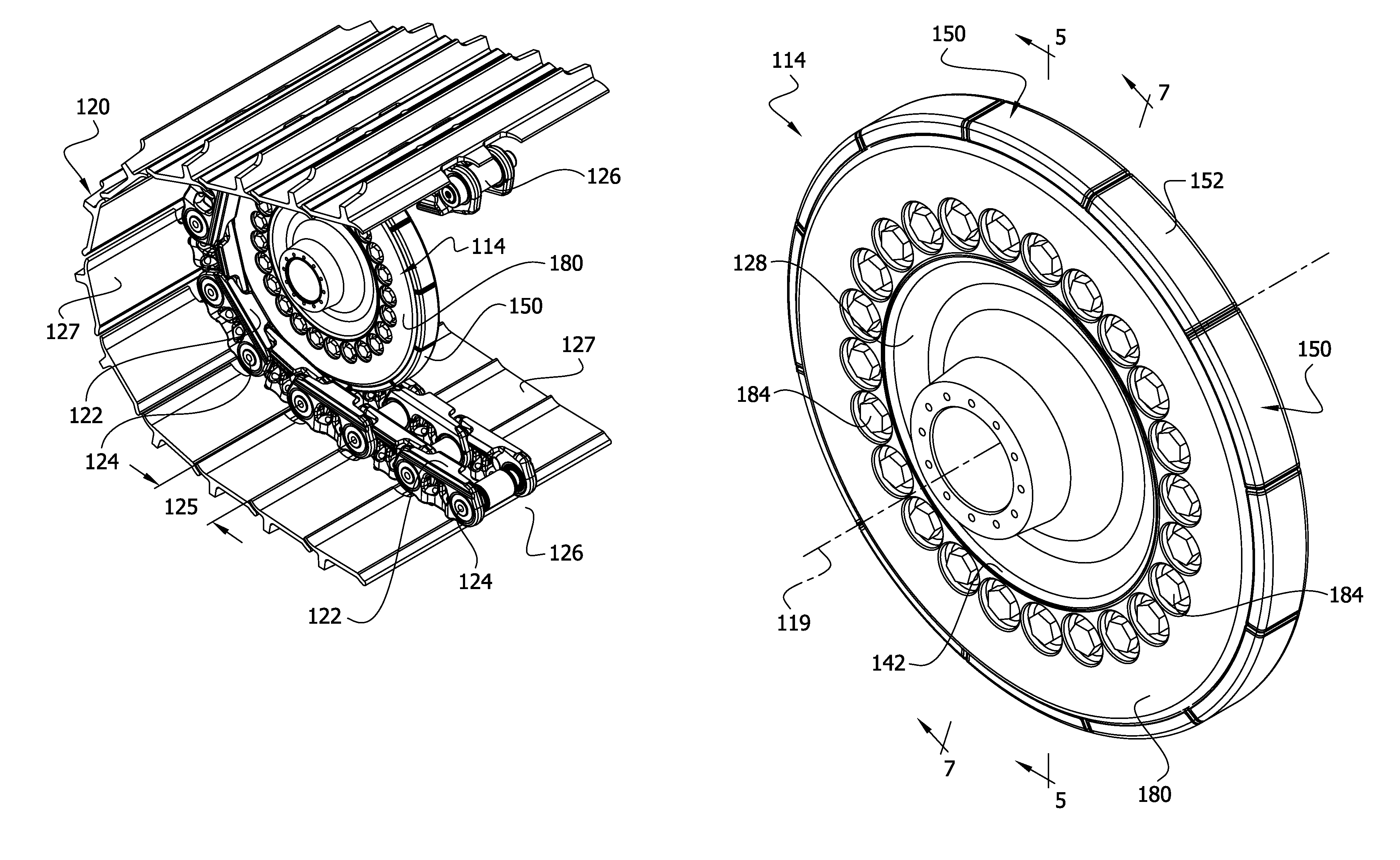
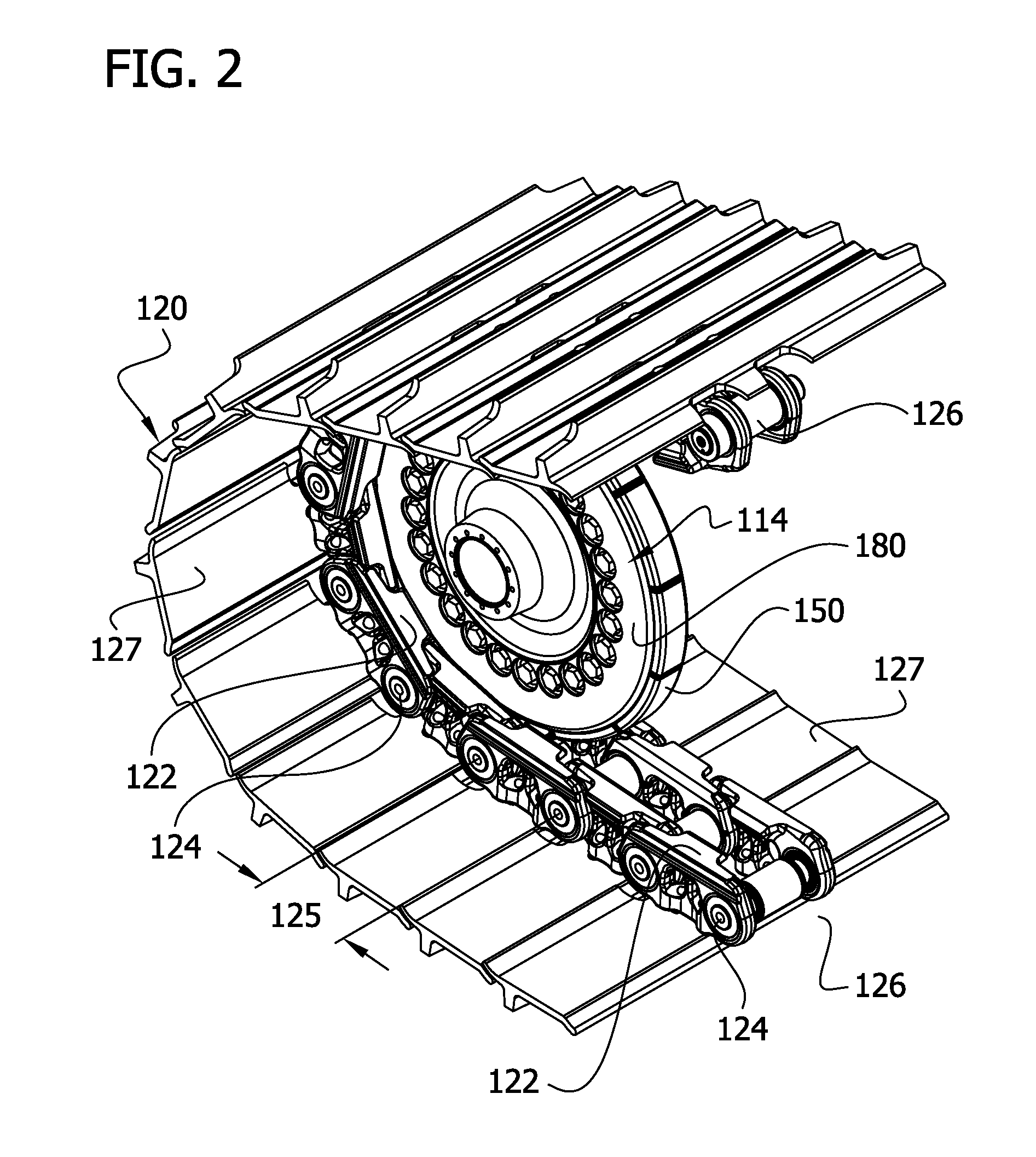
An idler having an axis of rotation. The idler may include a hub with a flange. A plurality of rim members are positioned along a perimeter of the flange and have generally axially facing, opposite side surfaces. At least one of the side surfaces has a first interlocking formation. A clamping plate is connected to the flange. The clamping plate has a second interlocking formation coupled with the first interlocking formation. A dampening member interposes the first and second interlocking formations.

Description

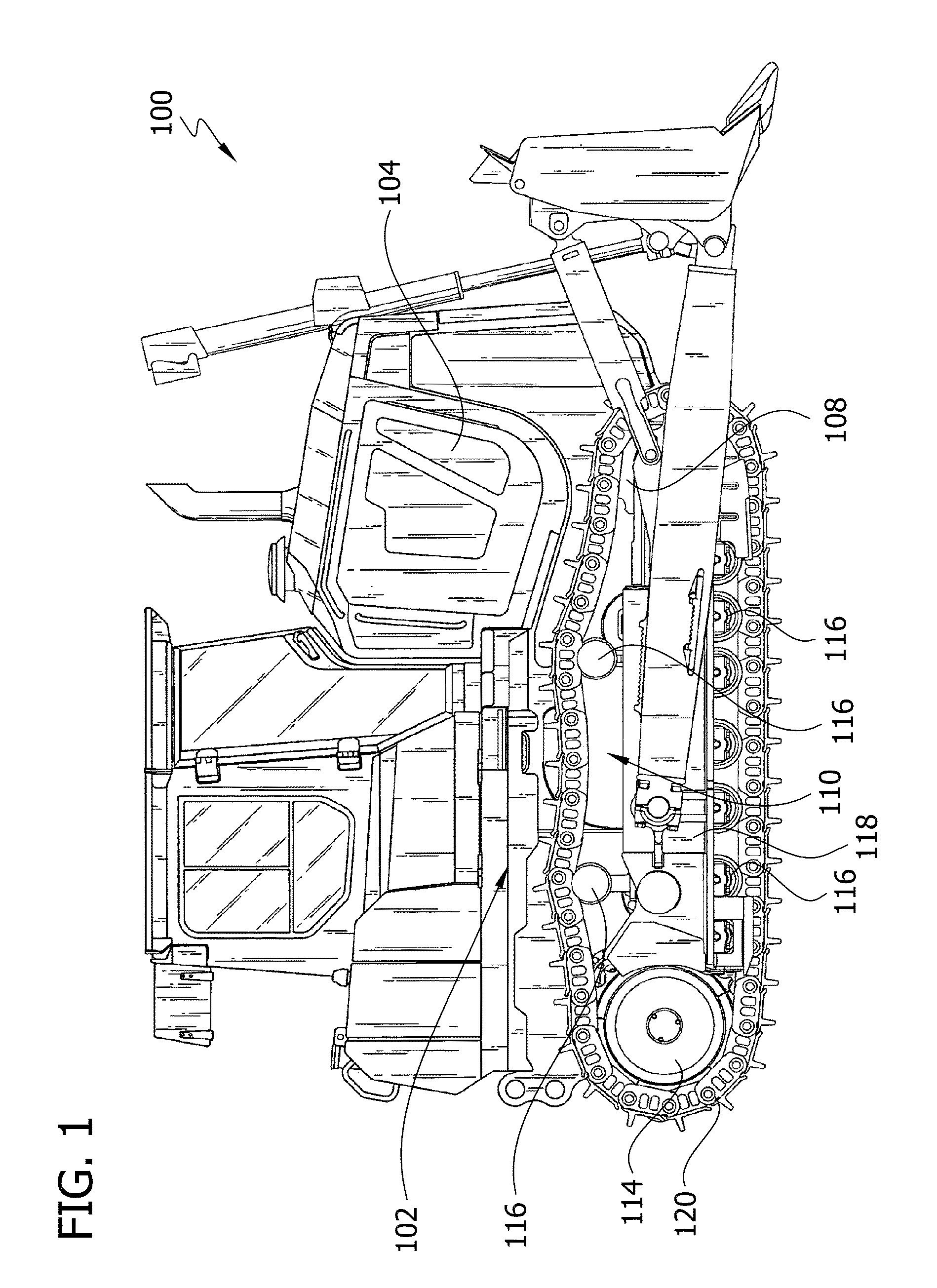
CROSS-REFERENCED TO RELATED APPLICATIONS[0001]This application claims benefit of U.S. Provisional Application No. 61 / 119,070 filed Dec. 2, 2008.TECHNICAL FIELD [0002]This disclosure relates generally to a tracked undercarriage, and more particularly, to an idler of the track undercarriage that provides sound suppression.BACKGROUND [0003]Operator comfort and noise regulations require reducing the sound decibel level emanating from a track-type machine. A source of noise in earth moving and construction track-type machines originates from the endless track chains as they revolve around and make contact with undercarriage components of the track-type machine. Idler wheels are used to guide and support portions of the track chains. Since these components are manufactured using metal, noise and vibration is generated between the track chains and the idler wheels during operation. This noise is then transmitted to, and typically amplified by, the hub of the idler wheel and the track chain...

Claims


Application Information

Patent Timeline
IPC IPC(8): B62D55/096F16H55/36B60B25/00
CPCB62D55/0966B62D55/32B62D55/145
Inventor JOHANNSEN, ERIC J.ANGOT, DANIEL D.JIANG, XIANGYANGZHANG, MINGBISSAHOYO, CONSTANT B.HAYS, ALEXANDER H.SNYDER, ANTHONY
Owner CATERPILLAR INC
Learn More