Prosthetic implant support structure

a technology of support structure and prosthesis, which is applied in the field of prosthetic devices, can solve the problems of loss of strong bone stock near the joint being replaced, cumbersome devices used to deliver bone grafts, and defects in bone adjacent to the joint, so as to facilitate bone ingrowth and attachment, and optimize the support of the implan

Inactive Publication Date: 2010-06-10
ZIMMER INC
View PDF50 Cites 80 Cited by
  • Summary
  • Abstract
  • Description
  • Claims
  • Application Information

AI Technical Summary

Benefits of technology

[0018]It is therefore an advantage of the present invention to provide prosthetic implant support structures that do not rely on the use of large amounts of bone graft or cumbersome bone graft delivery devices.
[0019]It is another advantage of the present invention to provide prosthetic implant support structures that can eliminate the need to cement the distal portion of the stem of an implant to the inner surface of a bone cavity.
[0020]It is a further advantage of the present invention to provide prosthetic implant support structures that can be used with a wide variety of prosthetic implants obtained from any number of different implant manufacturers.
[0021]It is yet another advantage of the present invention to provide a prosthetic implant system that optimizes implant support on intact host bone with minimal removal of residual host bone and that encourages bone ingrowth and attachment over as large a surface area as possible.
[0022]These and other features, aspects, and advantages of the present invention will become better understood upon consideration of the following detailed description, drawings, and appended claims.

Problems solved by technology

One problem commonly encountered by surgeons replacing joints is the loss of strong bone stock near the joint being replaced.
Defects in a bone adjacent a joint, such as the hip or knee, can occur due to wear and arthritis of the joint, congenital deformity, and following the removal of a failed prosthetic implant.
The use of bone graft to prepare a support surface for a prosthesis does have certain disadvantages as bone graft may not be readily available in all areas and the devices used to deliver bone graft can be quite cumbersome.
However, due to the large variation of bone quality, interdigitation of bone cement into the metaphyseal region is often suboptimal such that cement fixation of the stem in the bone cavity is necessary.
For example, one recognized problem with the use of a cemented stem is that the transfer of stress from the implant to the bone is abnormal.
Furthermore, the difficulties with sizing and bone graft preparation are cumbersome and inexact.
While these types of implant augmentation devices provide one solution to the problems associated with the implantation of a prosthesis in the end surface of a bone with inadequate bone stock, these implant augmentation devices can only be used with specific implants available from selected implant manufacturers.
In the context of hip arthroplasty, oversized acetabular components and morselized bone grafts have been used to restore bone deficiencies, but larger defects have in the past been associated with a high failure rate despite efforts at reconstruction using large solid structural allografts or custom acetabular components.
These devices gain support against the residual bone of the pelvis but often lack adequate bony support for long term mechanical durability.

Method used


Image

  • Prosthetic implant support structure
  • Prosthetic implant support structure
  • Prosthetic implant support structure

Examples


Embodiment Construction

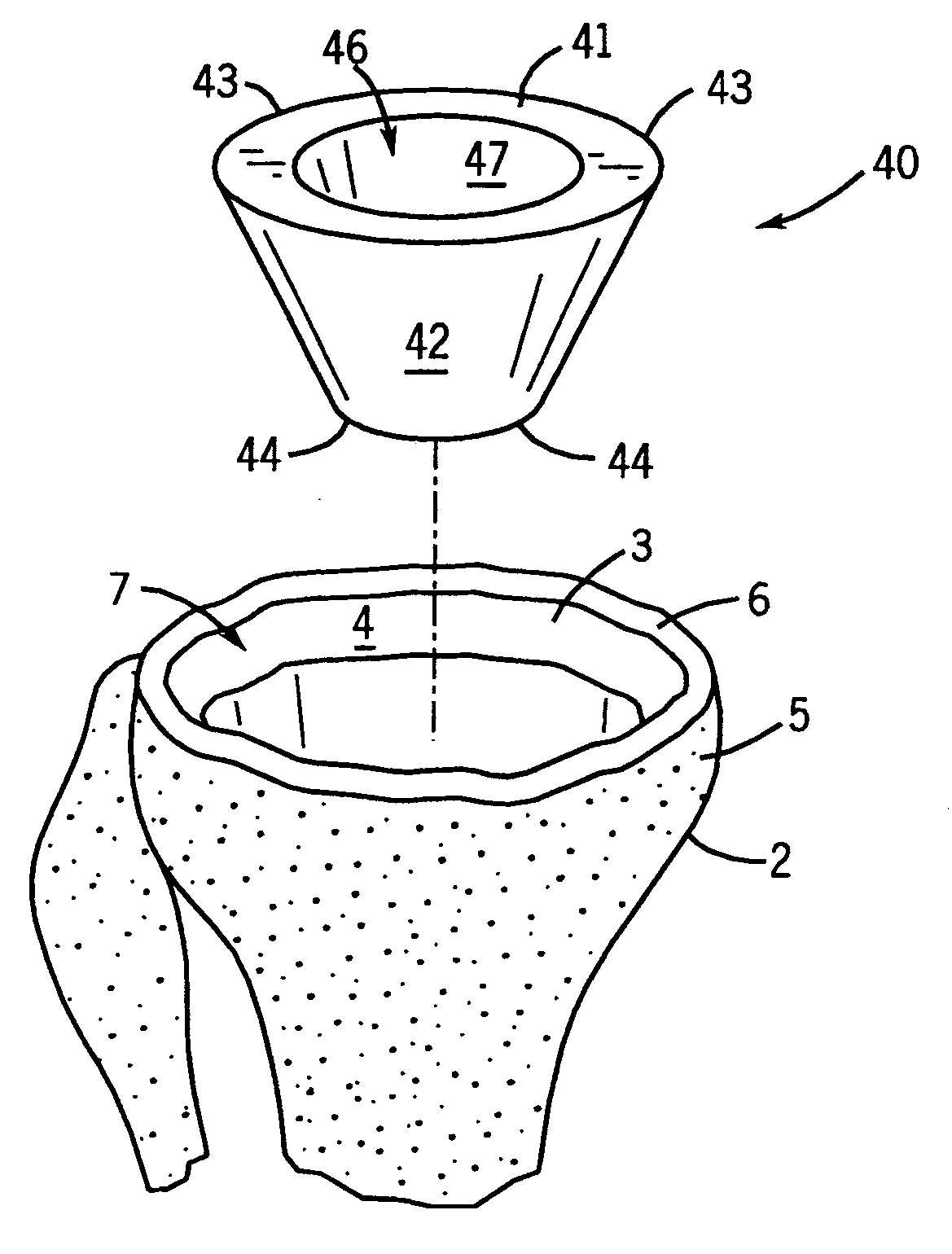
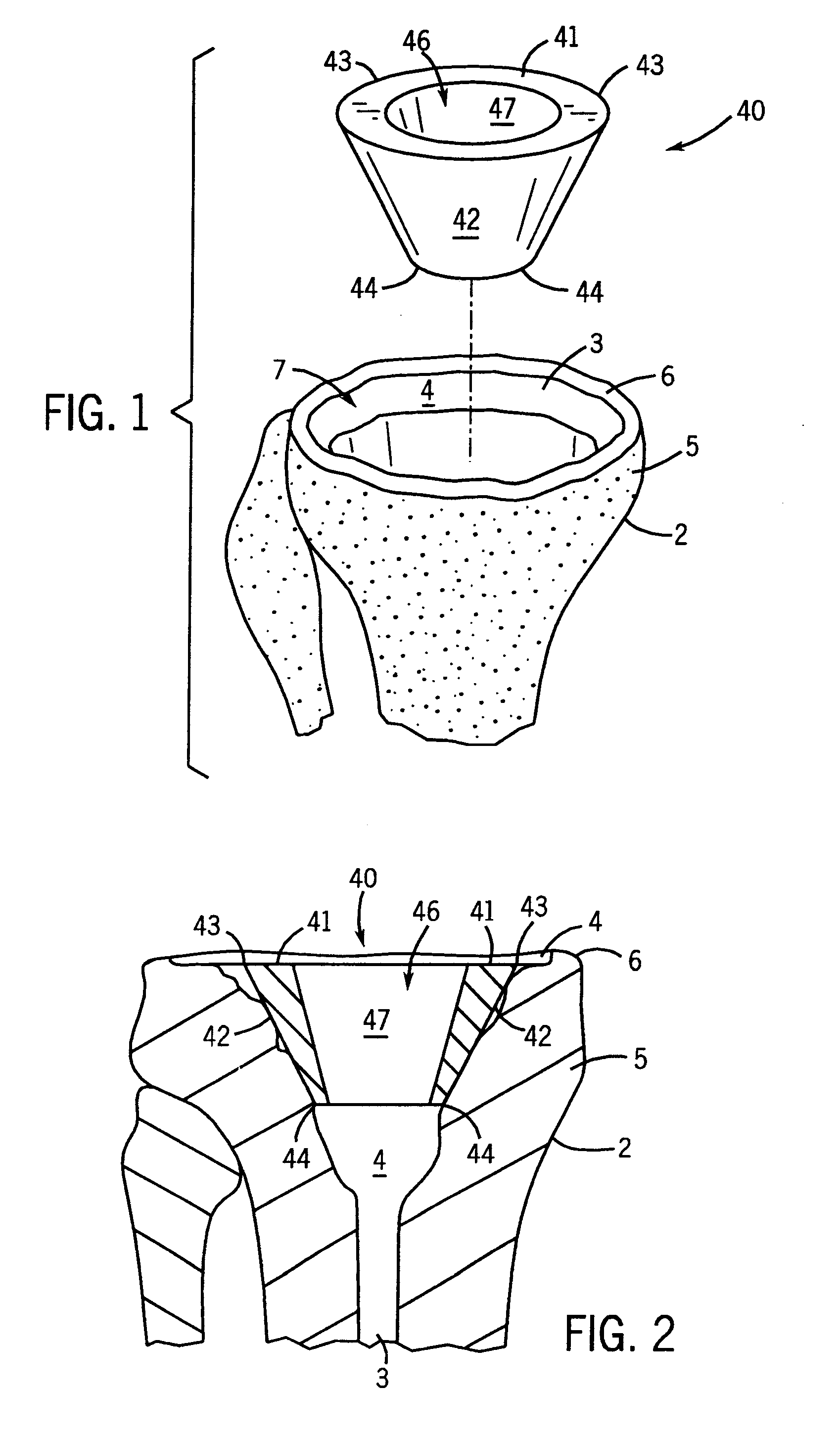
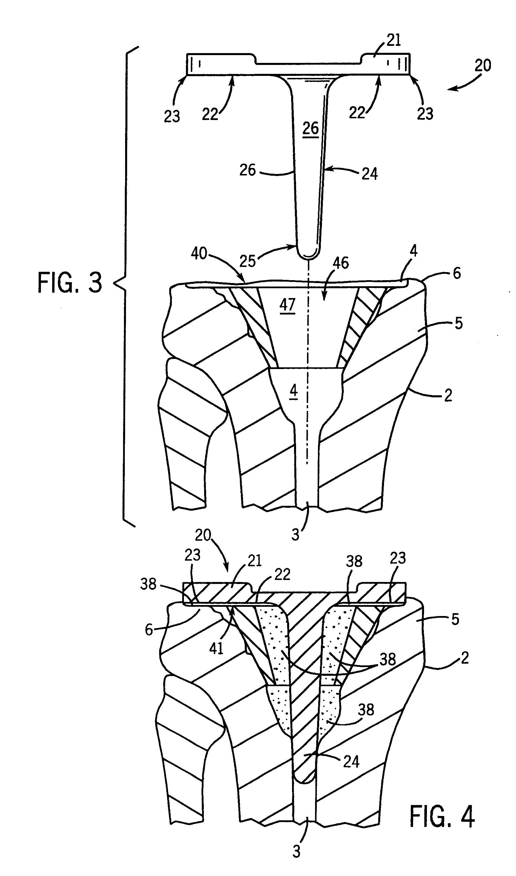
[0049]The present invention is directed to a prosthetic system that includes a prosthetic implant and a support structure secured to an inner surface of the cavity in the end of the bone. The prosthetic system and the methods for its use are illustrated and described herein with reference to the replacement of a hip joint or a knee joint. However, it should be understood that the methods and prosthetic systems according to the invention can be used in the repair of any bone or in connection with the implantation of prosthetic devices at or in any bone in the body, adjacent to or remote from any joint, including without limitation the hip, knee and spinal joints. Further, the methods and prosthetic systems according to the invention can be used in primary surgery, in which a prosthesis is being used to reconstruct a joint for the first time, as well as in revision surgery, in which a previously-implanted prosthesis is being replaced with another prosthesis. Press fit, cement or other...


PUM


Abstract

A prosthetic system that includes a prosthetic implant and a support structure secured to an inner surface of a cavity of a bone is disclosed. The support structure defines a channel that extends through the length of the support structure. The prosthetic implant is received in the channel, and a portion of the prosthetic implant is secured to an inner surface of the support structure by an adhesive. The support structure may comprise a pair of partially hemispherical components arranged in spaced apart relationship thereby defining the channel between the pair of components.

Description

CROSS-REFERENCE TO RELATED APPLICATIONS[0001]This is a divisional application of U.S. patent application Ser. No. 11 / 560,276 filed Nov. 15, 2006, which is a divisional application of U.S. patent application Ser. No. 10 / 225,774 filed Aug. 22, 2002, which claims the benefit of U.S. Provisional Patent Application No. 60 / 315,148 filed Aug. 27, 2001, the disclosures of which are hereby incorporated by reference herein in their entireties.STATEMENT REGARDING FEDERALLY SPONSORED RESEARCH[0002]Not Applicable.BACKGROUND OF THE INVENTION[0003]1. Field of the Invention[0004]This invention relates to prosthetic devices for implantation within a bone, and more particularly to support structures that are affixed to a bone and that support prosthetic implants.[0005]2. Description of the Related Art[0006]The replacement of joints, such as the shoulder, hip, knee, ankle and wrist, with prosthetic implants has become widespread. One problem commonly encountered by surgeons replacing joints is the los...

Claims


Application Information

Patent Timeline
Patent Type & Authority Applications(United States)
IPC IPC(8): A61F2/28A61B17/86A61B17/88A61F2/00A61F2/30A61F2/32A61F2/34A61F2/36A61F2/38A61F2/46
CPCA61B17/86A61F2/30A61F2/30767A61F2/30771A61F2/30965A61F2/34A61F2/36A61F2/3662A61F2/389A61F2002/2835A61F2002/30131A61F2002/30228A61F2002/30233A61F2002/30235A61F2002/30248A61F2002/30276A61F2002/30278A61F2002/30299A61F2002/30324A61F2002/30354A61F2002/30449A61F2002/30606A61F2002/30616A61F2002/30736A61F2002/30738A61F2002/30777A61F2002/30784A61F2002/30841A61F2002/30878A61F2002/3403A61F2002/3611A61F2002/3625A61F2002/3631A61F2002/4631A61F2002/4681A61F2220/0033A61F2220/005A61F2230/0013A61F2230/0069A61F2230/0071A61F2230/0086A61F2230/0093A61F2250/0036A61F2310/00017A61F2310/00023A61F2310/00029A61F2310/00131A61F2310/00203A61F2310/00239A61F2/30734A61F2002/30245A61F2002/30273A61F2002/30593
Inventor BLAYLOCK, JEFFCOOK, MICHAELDONKERS, RONDYKEMA, SCOTTHALL, MALEATAMEYERS, JOHNHANSSEN, ARLEN D.LEWALLEN, DAVID G.
Owner ZIMMER INC
Why Eureka
Try Eureka