System and method for optical locomotive decoupling detection

Inactive Publication Date: 2010-06-17
GENERAL ELECTRIC CO
View PDF20 Cites 63 Cited by
  • Summary
  • Abstract
  • Description
  • Claims
  • Application Information

AI Technical Summary

Benefits of technology

[0014]In an aspect of an exemplary method for determining whether a coupler of a locomotive engine is coupled as provided herein, a video camera is configured to provide video signals indicative of either a coupled or uncoupled state of the co

Problems solved by technology

The various services in a rail yard compete for resources such as personnel, equipment, and space in various facilities so that managing the entire rail yard efficiently is a complex operation.
For example, automated equipment identification (AEI) readers and AEI computers determine the location of rolling stock at points in the sequence of operations, but in general, this information is limited to data indicating rolling stock whereabou

Method used


Image

  • System and method for optical locomotive decoupling detection
  • System and method for optical locomotive decoupling detection
  • System and method for optical locomotive decoupling detection

Examples


Embodiment Construction

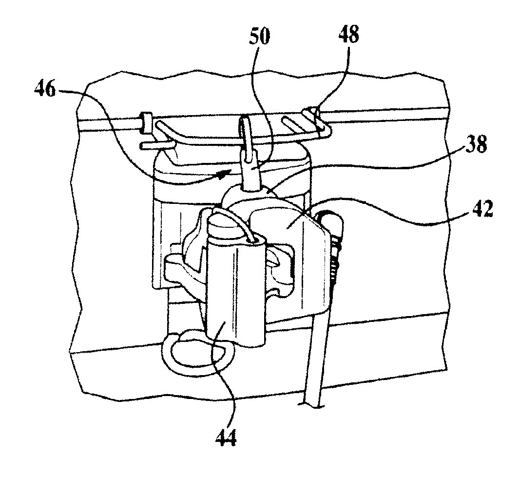
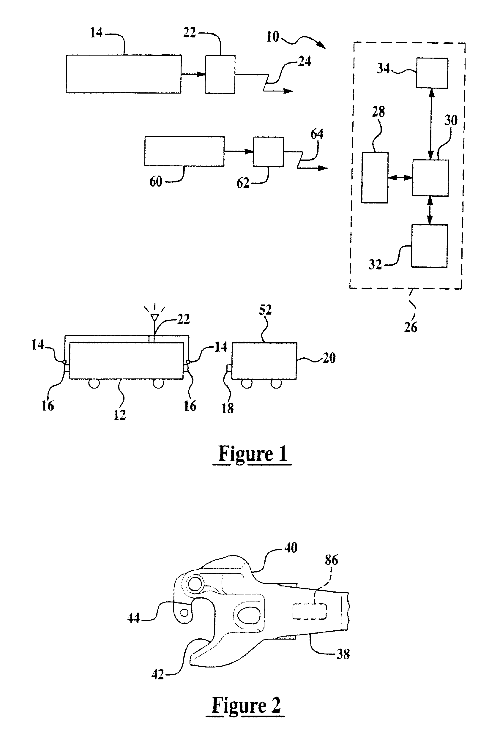
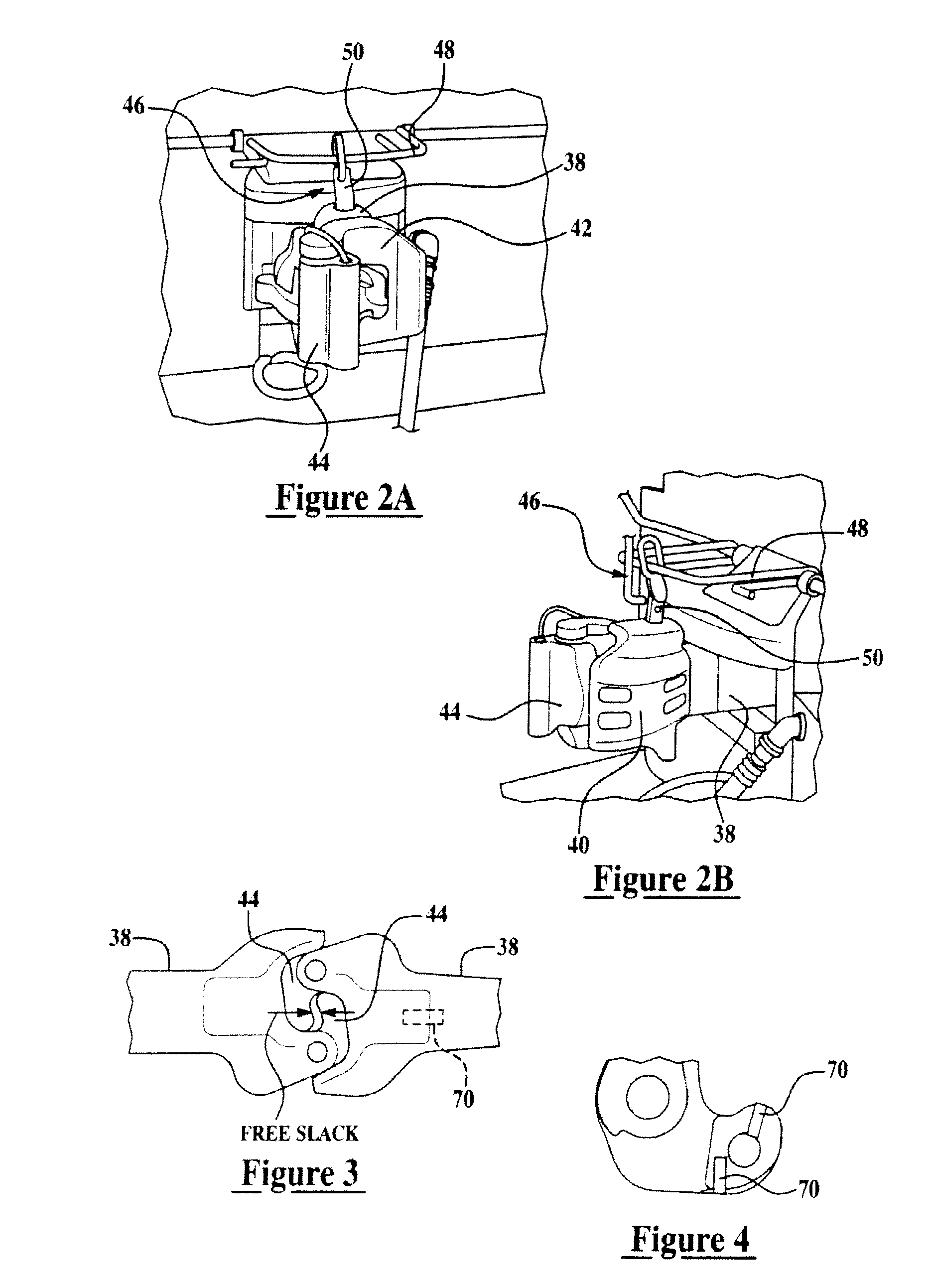
[0025]Exemplary embodiments of the systems and techniques described herein are directed to a system and method for robust determination of a locomotive's coupler status. In general, yard engines or locomotives are dedicated to moving road locomotives or other rail cars (e.g., cars that are pushed or pulled by locomotives) to and from different service and staging areas of a rail yard. Accordingly, it is desirable to know when a yard engine is coupled to a rail car or road locomotive. In accordance with an exemplary embodiment, sensors are provided to determine both a coupled state and an uncoupled state of the locomotive. The sensor output is conveyed over a wireless network to a control and monitoring system. In one exemplary embodiment the coupler sensor data may be combined with other data such as speed and direction of motion of the locomotive, which can also be provided wirelessly. This information allows assessment and utilization of the locomotive. Furthermore, the coupler st...


PUM


Abstract

An apparatus and method for indicating whether a coupler of a locomotive is in a coupled or uncoupled state is provided. The apparatus comprising: an optical sensor positioned on a portion of the coupler, wherein the sensor provides a real-time signal indicative of either a coupled or an uncoupled state of a coupler, wherein the signal is transmitted wirelessly by a transmitter in operable communication with the sensor. The method comprising: providing a signal indicative of the presence or proximity of a second coupler to the first coupler, the signal being provided by an optical sensor configured to provide the signal as the state of the coupler has changed; transmitting the signal wirelessly to a controller; processing the signal with a control algorithm resident upon the controller; and providing visually perceivable indication of the position of the coupler.

Description

CROSS-REFERENCE TO RELATED APPLICATIONS[0001]This application is a continuation-in-part of co-pending U.S. patent application Ser. No. 11 / 317,067 entitled “SYSTEM AND METHOD FOR DETERMINING WHETHER A LOCOMOTIVE OR RAIL ENGINE IS COUPLED TO A RAIL CAR OR OTHER ENGINE”, filed on 23 Dec. 2005, the entirety of which is incorporated by reference herein.TECHNICAL FIELD[0002]The systems and techniques described herein relate generally to rail yards, and more particularly to methods and apparatus for determining whether a train engine is coupled to a rail car.BACKGROUND[0003]Rail yards are the hubs of railroad transportation systems. Therefore, rail yards perform many services, for example, freight origination, interchange and termination, locomotive storage and maintenance, assembly and inspection of new trains, servicing of trains running through the facility, inspection and maintenance of railcars, and railcar storage. The various services in a rail yard compete for resources such as per...

Claims


Application Information

Patent Timeline
IPC IPC(8): B61L23/00
CPCB61G7/14B61L15/0054B61J3/00
Inventor BHOTIKA, RAHULWELLES, II, KENNETH BRAKELEYHERSHEY, JOHN ERIKDAVENPORT, DAVID MICHAEL
Owner GENERAL ELECTRIC CO
Why Eureka
Try Eureka