Magnetic inspection device

a magnetic inspection and non-destructive technology, applied in the direction of magnetic field measurement using galvano-magnetic devices, instruments, material magnetic variables, etc., can solve the problems of reducing the resolution of generated signals, limiting the application of devices, and the bulk and weight of most devices, so as to reduce secondary flux

Active Publication Date: 2010-06-17
NDT TECH LLC
View PDF8 Cites 45 Cited by
  • Summary
  • Abstract
  • Description
  • Claims
  • Application Information

AI Technical Summary

Benefits of technology

[0014]One aspect of the present invention resides in a magnetic inspection device for nondestructively detecting structural faults and discontinuities in elongated magnetically permeable objects such as wire cables, rods, pipes, tank, walls, ship hulls, and the like. The magnetic inspection device has a magnet with two opposite magnetic poles spaced apart from one another at longitudinally spaced stations for positioning and movement relative to an elongated magnetically permeable object to be inspected. The magnet induces in the sections between the stations magnetic flux at the saturation level. The magnet also defines a ferromagnetic flux return path between the poles externally of the object for completing a flux circuit. The magnetic inspection device has a magnetic sensor assembly that has a magnetic flux detector. The magnetic flux detector is positioned between the poles and stations adjacent to the elongated object. The sensing portion of the magnetic flux detector faces the surface of the elongated object between the two poles of the magnet for sensing perturbations in leakage flux at the exterior surface caused by discontinuities in the object. The sensing of perturbations is done as the object and the inspection device move relative to one another. Further, the magnetic inspection device has a flux decompressor located between the magnetic poles of the magnet and adjacent the magnetic flux detector for reducing secondary flux at the surface of the object in the vicinity of the detector and allowing a more pronounced expression or drawing out of leakage flux at the surface of the object due to the fault or discontinuity.
[0015]Another aspect of the present invention has a flux shield in the vicinity of the magnetic flux detector. The flux shield is located between the magnetic sensor assembly and each pole of the magnet. The flux shields absorb secondary flux between the poles in the vicinity of the flux detector to aid the magnetic sensor assembly in sensing the perturbations of leakage flux.
[0017]Another aspect of the present invention resides in a method for nondestructively inspecting an elongated magnetically permeable object that includes a magnetic flux decompression step. A magnetic field is induced in the elongated magnetically permeable object between longitudinally spaced poles at the saturation level. A magnetic sensor assembly having a magnetic flux detector is provided to detect leakage flux at the surface of the object. The flux between the magnetic poles in the vicinity of the magnetic flux detector is decompressed in and around the object, while the magnetic field and spaced poles move progressively longitudinally along the object to allow a more pronounced expression of leakage flux at the exterior surface of the object due to changes in metallic cross section.

Problems solved by technology

Serious accidents, various non-scheduled equipment downtimes, and premature replacement as precautionary measures are all consequences of the state of the art, quite apart from the costs involved in the inspection process.
One of the primary problems in prior art magnetic inspecting devices is the bulk and weight of most of the devices.
Both of these factors limit the applications of the devices and reduce the resolution of the signals that are generated.
Test signals are complex and are frequently accompanied by high levels of noise due to non-homogeneities and the coarse construction of objects under test.
Both of these discontinuities cause a reduction in metallic cross section and, consequently, affect cable life and strength.
One of the disadvantages, however, is that an extended section of the cable is inspected at any given moment.
Therefore, only the average value of the metallic cross sectional area is measured with a considerable loss of resolution.
Also, small flaws, such as those caused by broken wires or cluster of wires, and other localized discontinuities are difficult to detect.
The disadvantages of the prior art systems are that the reduction in cross-sectional area caused by abrasion and corrosion cannot be determined quantitatively, and since the measurements are representative of changes in the leakage flux, signal amplitudes for coils are proportional to the test speeds.
This adds complexity and weight to the instruments, and additionally, a certain minimum speed is generally required for a threshold signal.
Because of the non-homogeneous structure of wire cabling, test signals are very noisy, and the noise signal cannot be removed by filtering because the differences in the levels of the noise and flaw signals are very small.
Still further, because of the requirement for movement between the magnetic device and the cable, the process cannot be carried out at the ends of a cable, which is permanently secured in place.
The disadvantage of a system using sensing coils is that the coil sensors require fairly elaborate electronic analog circuitry that cannot be accommodated on the sensor head.
The problem with all of the patents listed above is that there is a strong presence of secondary flux between the magnetic poles that can affect the sensitivity of the magnetic flux detector and makes the accurate detection of loss of metallic cross section or localized discontinuities difficult.

Method used


Image

  • Magnetic inspection device
  • Magnetic inspection device
  • Magnetic inspection device

Examples


Embodiment Construction

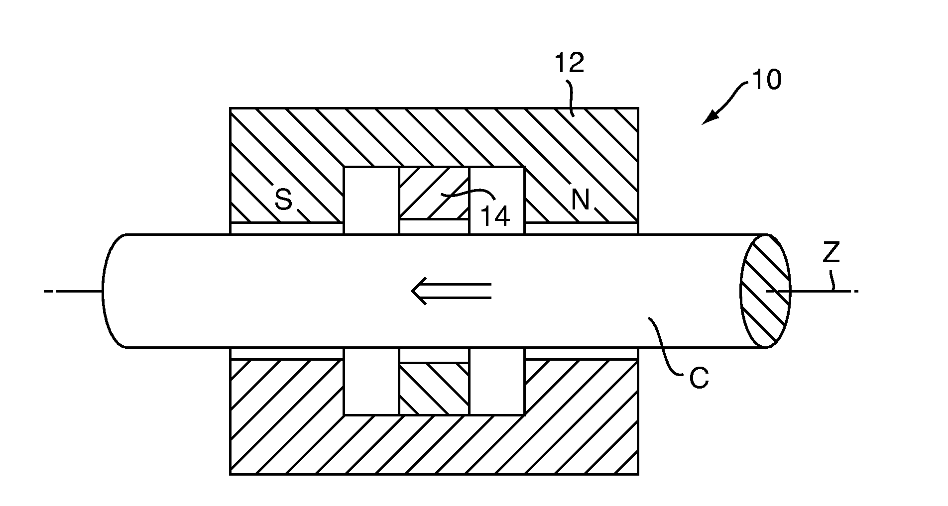
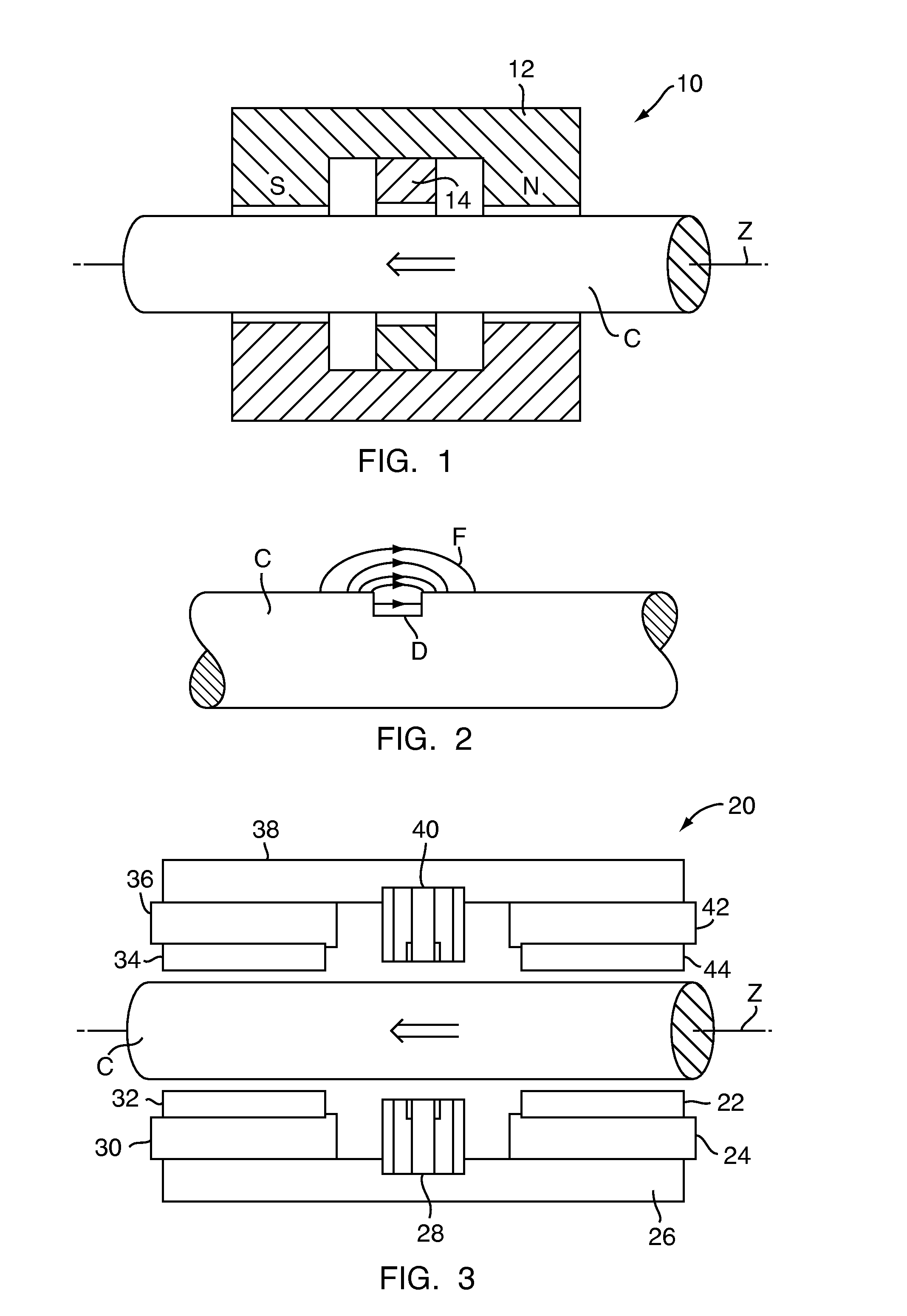
[0033]FIG. 1 illustrates a section of a magnetic inspection device 10 for nondestructively detecting loss of metallic cross section in elongated ferromagnetic objects such as but not limited to a wire cable C. Loss in metallic cross section can occur due to abrasion through use, corrosion, and also due to local discontinuities such as fractures or breakage of individual wires on the exterior surface of the cable C or internally. The magnetic device 10 may be used to inspect cables C or the like, either in the manufacturing process or in a working environment without removing the cable C from its normal operating position. The magnetic device 10 may also be used for inspecting other types of elongated, magnetically permeable objects, such as pipes, rods, bars, billets, storage tanks, hulls, and the like.

[0034]The magnetic device 10 is comprised of a permanent magnet or magnets 12 for inducing a saturated magnetic field axially through the cable C in the longitudinal direction. The pe...


PUM

PropertyMeasurementUnit
supply voltageaaaaaaaaaa
magnetic inspectionaaaaaaaaaa
magnetic fluxaaaaaaaaaa

Abstract

A magnetic inspection device for nondestructively inspecting elongated objects, such as wire cables, pipes, and the like, for loss of metallic cross-section due to abrasion, corrosion, and external and internal discontinuities, having a magnet for inducing in sections of the object between the stations, magnetic flux at the saturation level. A magnetic flux detector having magnetic sensors positioned between the poles and laterally of the elongated object utilizes shields and flux decompressors to render the flux detector more sensitive to leakage flux caused by discontinuities in the objects.

Description

STATEMENT REGARDING FEDERALLY SPONSORED RESEARCH[0001]This invention was made with government support under Contract Nos. N62473-07-C-4088 and N00244-07-C-0064 awarded by the Department of Navy. The government has certain rights in the invention.FIELD OF THE INVENTION[0002]The present invention relates to nondestructive magnetic inspection devices for evaluating elongated objects such as wire cables, rods, pipes, and the like, and is concerned more particularly with a magnetic testing method and device for detecting loss in metallic cross section in the objects due to distributed or localized discontinuities on the surface or within the object. The invention may be utilized both at the manufacturing level and / or in the field.BACKGROUND OF THE INVENTION[0003]Reliable and rational techniques for assessing the condition of wire cabling, rods, pipes, and similar elongated ferromagnetic objects such as visual and electromagnetic inspections are known in the art, but depend extensively on...

Claims


Application Information

Patent Timeline
Patent Type & Authority Applications(United States)
IPC IPC(8): G01N27/90G01N27/72
CPCG01N27/9033G01N27/9006
Inventor WEISCHEDEL, HERBERT R.
Owner NDT TECH LLC
Why Eureka
Try Eureka