
Signal transmitting device, signal transmitting method, signal receiving device, and signal receiving method

Active Publication Date: 2010-06-17
SONY CORP
View PDF22 Cites 36 Cited by
  • Summary
  • Abstract
  • Description
  • Claims
  • Application Information

AI Technical Summary

Benefits of technology

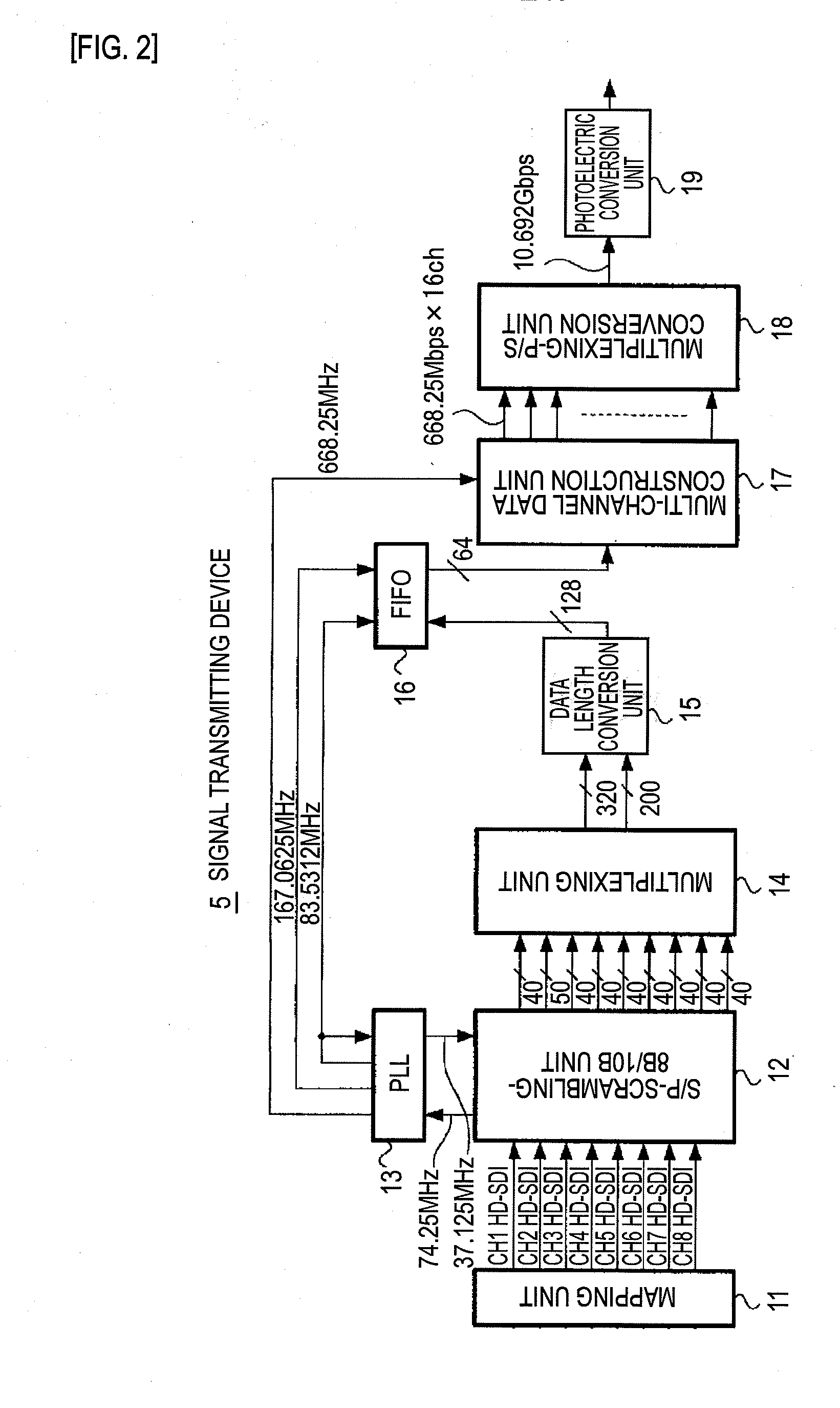
[0025]According to the present invention, each of pixel samples of an image signal in which the number of pixels of one frame is larger than the number of pixels specified in the HD-SDI format is mapped into channels having a serial digital video signal format conformable to the HD-SDI format. Thus, the signal can be converted into serial digital data permitting a bit rate of 10.692 Gbps or the like and transmitted, and the receiving side can accurately reproduce original data. Therefore, this is advantageous in that an ultra-high-definition video signal can be transmitted by using a conventional interface.

Problems solved by technology

However, in the SMPTE or ITU, frames of 3840 samples×2160 lines or 7680 samples×4320 lines are standardized, but interfaces thereof are not standardized.
Since an image signal of a transmission rate exceeding the HD-SDI format has an extremely large data volume, the image signal cannot be transmitted in real time by using only one channel of existing transmission system.

Method used


Image

  • Signal transmitting device, signal transmitting method, signal receiving device, and signal receiving method
  • Signal transmitting device, signal transmitting method, signal receiving device, and signal receiving method
  • Signal transmitting device, signal transmitting method, signal receiving device, and signal receiving method

Examples


first embodiment

[0047]Referring to FIG. 1 to FIG. 18, the present invention will be described below.

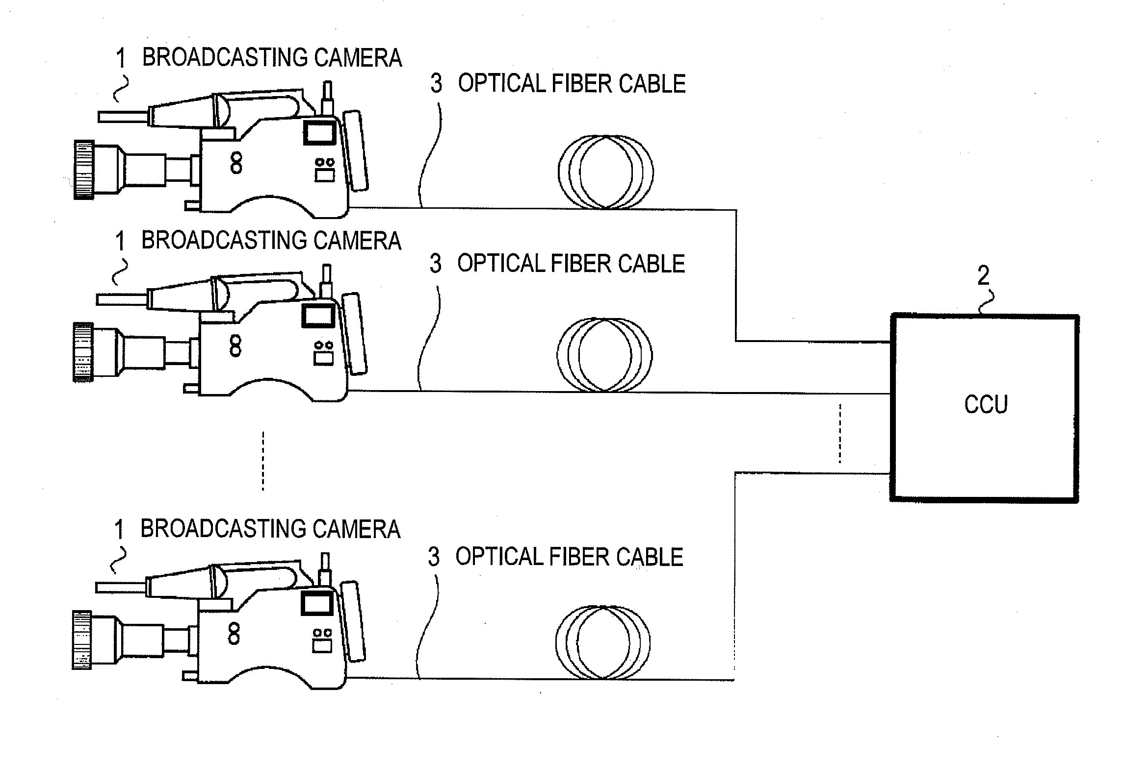
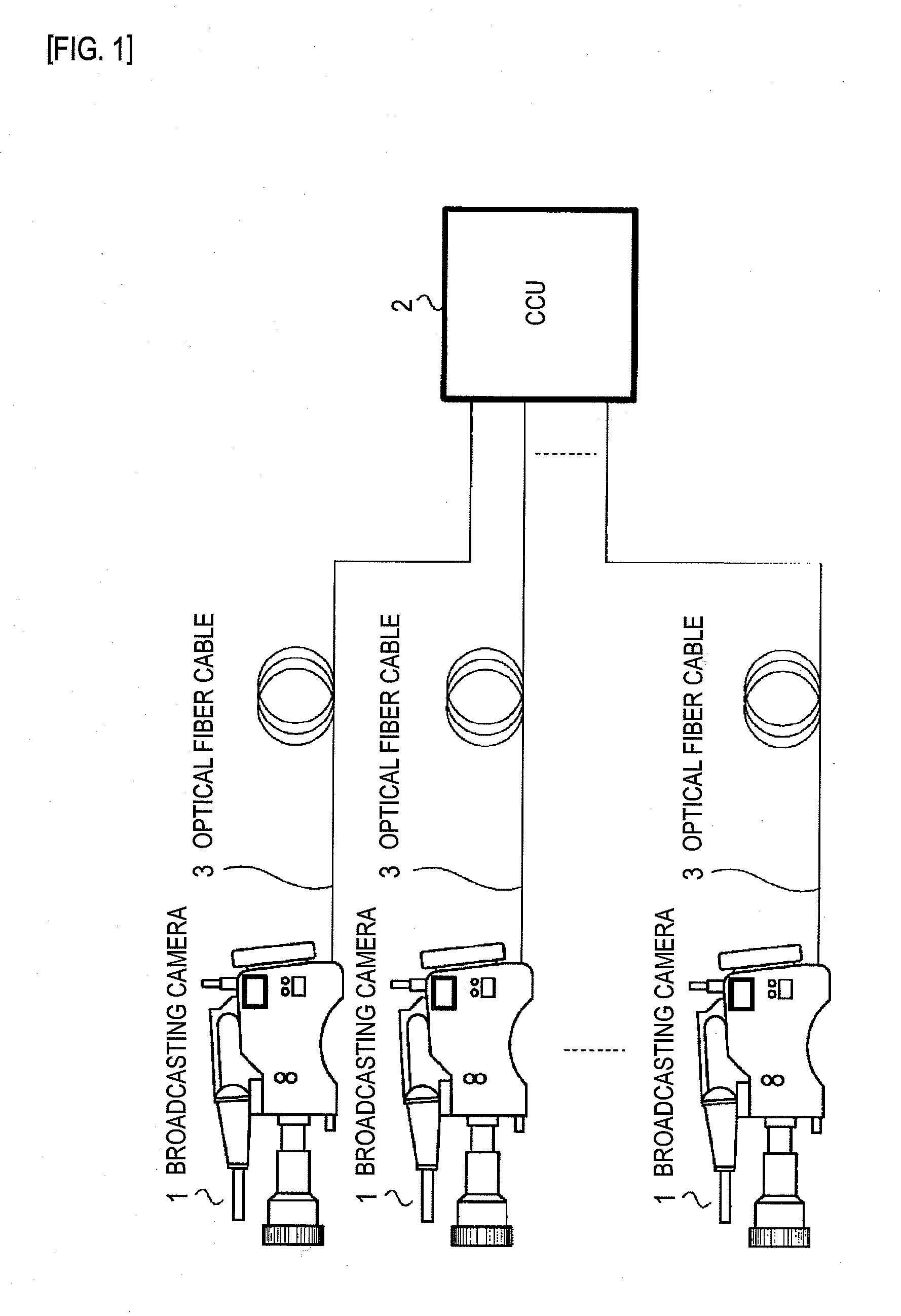
[0048]FIG. 1 is a diagram showing an overall constitution of a camera transmission system for television broadcasting stations to which the present embodiment is adapted. The camera transmission system includes multiple broadcasting cameras 1 and a camera control unit (CCU) 2. The broadcasting cameras 1 are connected to the CCU 2 over optical fiber cables 3.

[0049]The broadcasting cameras 1 are cameras that share the same constitution and function as signal transmitting devices that produce and transmit as a 4 k×2 k signal (an ultra-high-definition signal of 4 k samples×2 k lines) a 3840×2160 / 24P,25P,30P / 4:4:4,4:2:2,4:2:0 / 10,12-bit signal equivalent to an LSDI signal.

[0050]The CCU 2 is a unit that controls each of the broadcasting cameras 1, receives a video signal from each of the broadcasting camera 1, or transmits a video signal (return video) to be used to display on a monitor of each of the broad...

second embodiment

[0202]Next, an example of actions of a mapping unit 11 included in the present invention will be described with reference to FIG. 19.

[0203]FIG. 19 is an explanatory diagram showing an example in which samples constituting one frame of a 4 k×2 k signal are mapped into first to fourth sub-images by the mapping unit 11.

[0204]In the present embodiment, the mapping unit 11 characteristically maps a 3840×2160 / 50P,60P / 4:4:4,4:2:2,4:2:0 / 10,12-bit signal into the first to fourth sub-images. The other components are identical to those of the first embodiment. An iterative description will be omitted. As for the processing of a signal receiving device 6 included in a CCU 2, since it is identical to that in the first embodiment, an iterative description will be omitted.

[0205]A broadcasting camera 1 in this example is a camera including a signal transmitting device 5 that produces a 3840×2160 / 50P,60P / 4:4:4,4:2:2,4:2:0 / 10,12-bit signal, which is equivalent to a signal specified in the UHDTV1, as ...

third embodiment

[0216]Next, referring to FIG. 20, an example of actions of a mapping unit 11 included in the present invention will be described below.

[0217]FIG. 20 is an explanatory diagram showing an example in which samples constituting one frame of a 8 k×4 k signal are mapped into first to fourth sub-images by the mapping unit 11.

[0218]In the present embodiment, the mapping unit 11 maps a 7680×4320 / 50P,60P / 4:4:4,4:2:2,4:2:0 / 10,12-bit signal into first to fourth sub-images. The other components are identical to those of the first embodiment. Therefore, an iterative description will be omitted.

[0219]A broadcasting camera 1 in this example is a camera including a signal transmitting device 5 that produces a first frame, which is specified with a 7680×4320 / 50P,60P / 4:4:4,4:2:2,4:2:0 / 10,12-bit signal equivalent to a UHDTV2 signal, as a frame of a 8 k×4 k signal (an ultra-high-definition signal representing 8 k samples×4 k lines), and transmits HD-SDI signals into which the signal is mapped according ...


PUM


Abstract

For example, samples included in a frame constituted by a 3840×2160 / 24P,25P,30P / 4:4:4,4:2:2,4:2:0 / 10,12-bit signal are mapped into first to fourth sub-images specified in the HD-SDI format, in units of two adjoining samples. Thus, it is possible to transmit through a transmission constitution for the HD-SDI format. The signal can be converted into serial digital data permitting a bit rate of 10.692 Gbps or the like and transmitted, and the receiving side can accurately reproduce original data.

Description

TECHNICAL FIELD[0001]The present invention relates to a signal transmitting device, signal transmitting method, a signal receiving device and a signal receiving method for serially transmitting an image signal, in which the number of pixels of one frame is larger than the number of pixels specified in the HD-SDI format.BACKGROUND ART[0002]Development of an image receiving system and an imaging system that handle an ultra-high-definition video signal which overwhelms a high-definition (HD) signal, that is, an existing image signal (video signal) in which one frame has 1920 samples on each of 1080 lines has made progress. For example, ultra-high-definition television (UHDTV) specifications that constitute a new-generation broadcasting method of handling four times or sixteen times larger the number of pixels than an existing HD broadcasting method have been proposed to or standardized by the International Telecommunication Union (ITU) or the Society of Motion Picture and Television En...

Claims


Application Information

Patent Timeline
IPC IPC(8): H04N7/01H04J3/00H04N5/225H04N7/08H04N7/173
CPCH04N7/015H04N7/12H04N21/440263H04N21/23602H04N21/4342H04N21/234363
Inventor YAMASHITA, SHIGEYUKI
Owner SONY CORP
Learn More