
Optical Pressure Switch, Door Operating System and Method

a technology of optical pressure switch and operating system, which is applied in the direction of optical radiation measurement, instruments, wing accessories, etc., can solve the problems of reducing the reliability or sensitivity of switches, mechanical contact components of mechanical pressure wave switches have no self-cleaning capabilities, and insufficient to keep these mechanical contacts clean

Active Publication Date: 2010-06-24
JEC OPTICS
View PDF37 Cites 9 Cited by
  • Summary
  • Abstract
  • Description
  • Claims
  • Application Information

AI Technical Summary

Benefits of technology

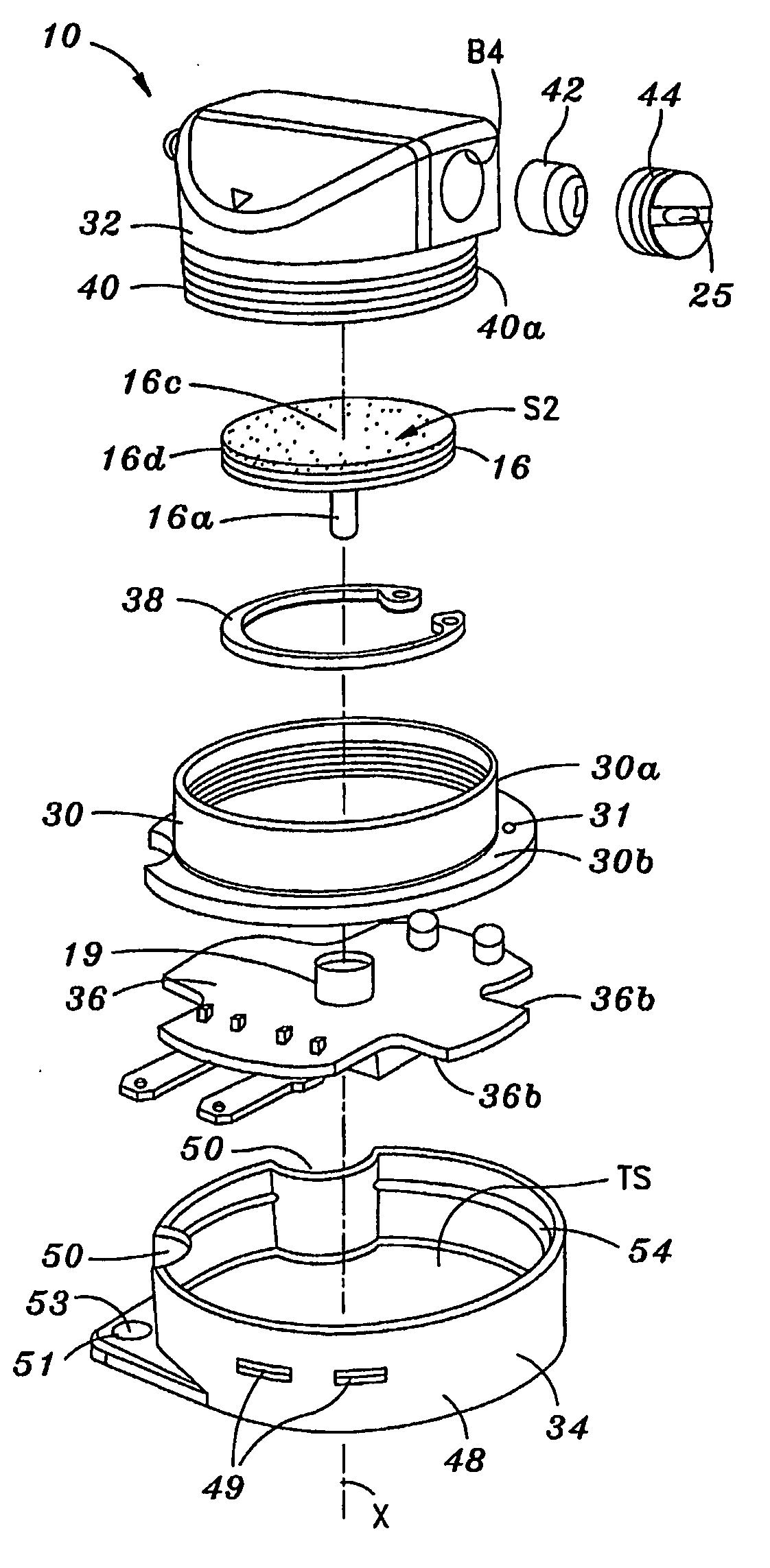
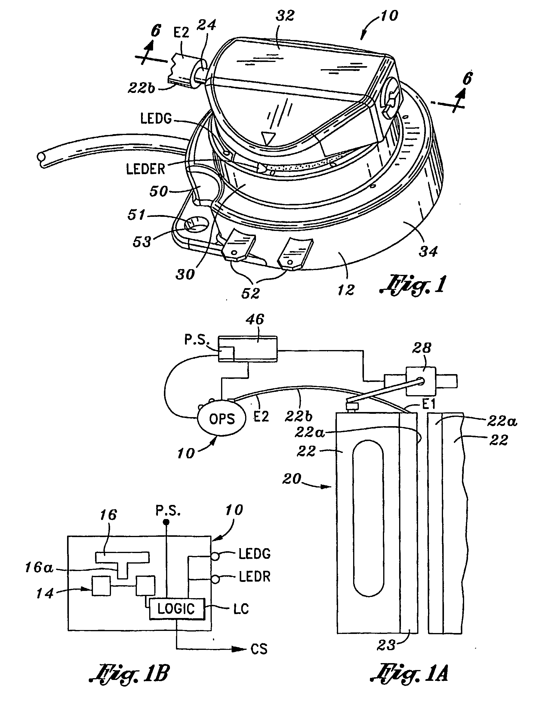
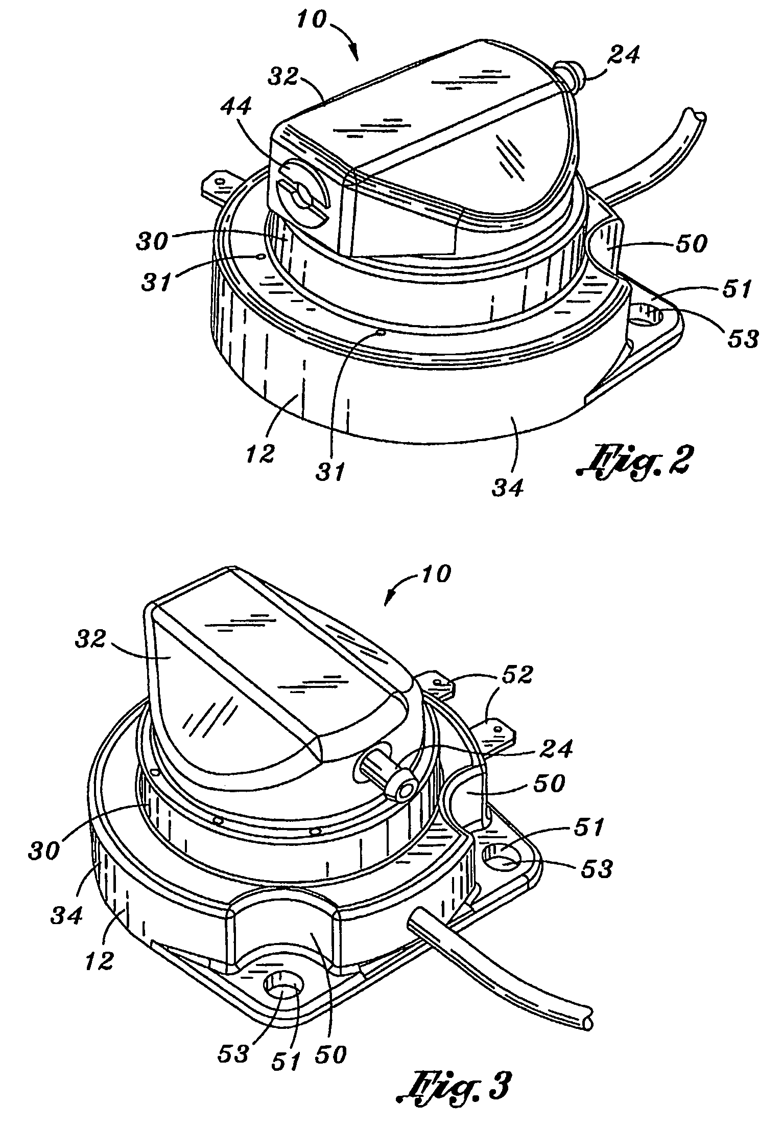
[0005]This invention has one or more features as discussed subsequently herein. After reading the following section entitled “DETAILED DESCRIPTION OF SOME EMBODIMENTS OF THIS INVENTION,” one will understand how the features of this invention provide its benefits. The benefits of this invention include, but are not limited to providing: an optical pressure wave switch having greater stability and reliability under environmental contaminating conditions; an optical pressure wave switch that is easy to calibrate or re-calibrate; an optical pressure wave switch that is less sensitive to environmental contamination, and therefore, will remain calibrated longer creating a longer life; and an optical pressure wave switch that is electronic rather than a mechanical type, and optionally, may have the ability for self annunciation for purposes of diagnostic testing.
[0011]Five, in one embodiment of this invention, one chamber includes the optically activated control device and is open to ambient pressure through a restricted opening that substantially reduces contamination of the optically activated control device that would interfere with the functioning of the light beam. This chamber is substantially closed to the atmosphere and houses or encloses essentially the entire optically activated control device, or at least the optical elements of the device. This protects the optical elements to reduce significantly environmental contamination.

Problems solved by technology

Such conventional mechanical pressure wave switches typically use two mechanical metallic contacts that are subject to oxidation and other environmental contamination that can reduce the reliability or sensitivity of the switches, as well as creating a failure condition.
The mechanical contact components of mechanical pressure wave switches have no self-cleaning capabilities such as contact wiping.
Moreover, the mechanical contacts pass very low current (approximately 12-18 milliamps) which is not enough to keep these mechanical contacts clean.

Method used


Image

  • Optical Pressure Switch, Door Operating System and Method
  • Optical Pressure Switch, Door Operating System and Method
  • Optical Pressure Switch, Door Operating System and Method

Examples


Embodiment Construction

,” one will understand how the features of this invention provide its benefits. The benefits of this invention include, but are not limited to providing: an optical pressure wave switch having greater stability and reliability under environmental contaminating conditions; an optical pressure wave switch that is easy to calibrate or re-calibrate; an optical pressure wave switch that is less sensitive to environmental contamination, and therefore, will remain calibrated longer creating a longer life; and an optical pressure wave switch that is electronic rather than a mechanical type, and optionally, may have the ability for self annunciation for purposes of diagnostic testing.

[0006]Without limiting the scope of this invention as expressed by the claims that follow, some, but not necessarily all, of its features are:

[0007]One, the optical pressure switch of this invention includes a body having a passageway therein, a flexible membrane in fluid communication with the passageway, and a...


PUM


Abstract

A door having a pneumatic sensing edge is operated automatically to open when an object and the edge make contact An optical pressure switch (10) in fluid communication with gas forced from the edge on contact with the object initiates the operation of a door opener The optical pressure switch (10) includes a membrane (16) having a portion that interrupts a light beam (LB) when the membrane (16) flexes due to the increase gas pressure over ambient pressure as gas is forced from the edge

Description

INCORPORATION BY REFERENCE[0001]The inventors incorporate herein by reference any and all U.S. patents, U.S. patent applications, and other documents, hard copy or electronic, cited or referred to in this application.DEFINITIONS[0002]The words “comprising,”“having,”“containing,” and “including,” and other forms thereof, are intended to be equivalent in meaning and be open ended in that an item or items following any one of these words is not meant to be an exhaustive listing of such item or items, or meant to be limited to only the listed item or items.BACKGROUND OF INVENTION[0003]Automatic door operating systems are commonly used in vehicles such as passenger transit buses and rail cars, for example. The door or doors of such systems have a pneumatic sensing edge connected by a gas conduit or hose to a pressure wave switch included in an electrical control circuit for the door operating system. When the sensing edge makes momentary contact with an object on closure of the door, a p...

Claims


Application Information

Patent Timeline
Patent Type & Authority Applications(United States)
IPC IPC(8): E05F1/00G01J1/56
CPCH01H2239/022H01H35/24
Inventor CONDON, JAMES E.CONDON, CLARE M.BECK, GREGORY S.
Owner JEC OPTICS
Learn More