Electrical connector assembly with antenna function

a technology of connectors and antennas, applied in the direction of resonant antennas, substantially flat resonant elements, coupling device connections, etc., can solve the problems of electronic devices trending towards miniaturization and other directions

Inactive Publication Date: 2010-07-01
HON HAI PRECISION IND CO LTD
View PDF4 Cites 48 Cited by
  • Summary
  • Abstract
  • Description
  • Claims
  • Application Information

AI Technical Summary

Problems solved by technology

However, electronic devices tren

Method used


Image

  • Electrical connector assembly with antenna function
  • Electrical connector assembly with antenna function
  • Electrical connector assembly with antenna function

Examples


Embodiment Construction

[0015]Reference will now be made in detail to the preferred embodiment of the present invention.

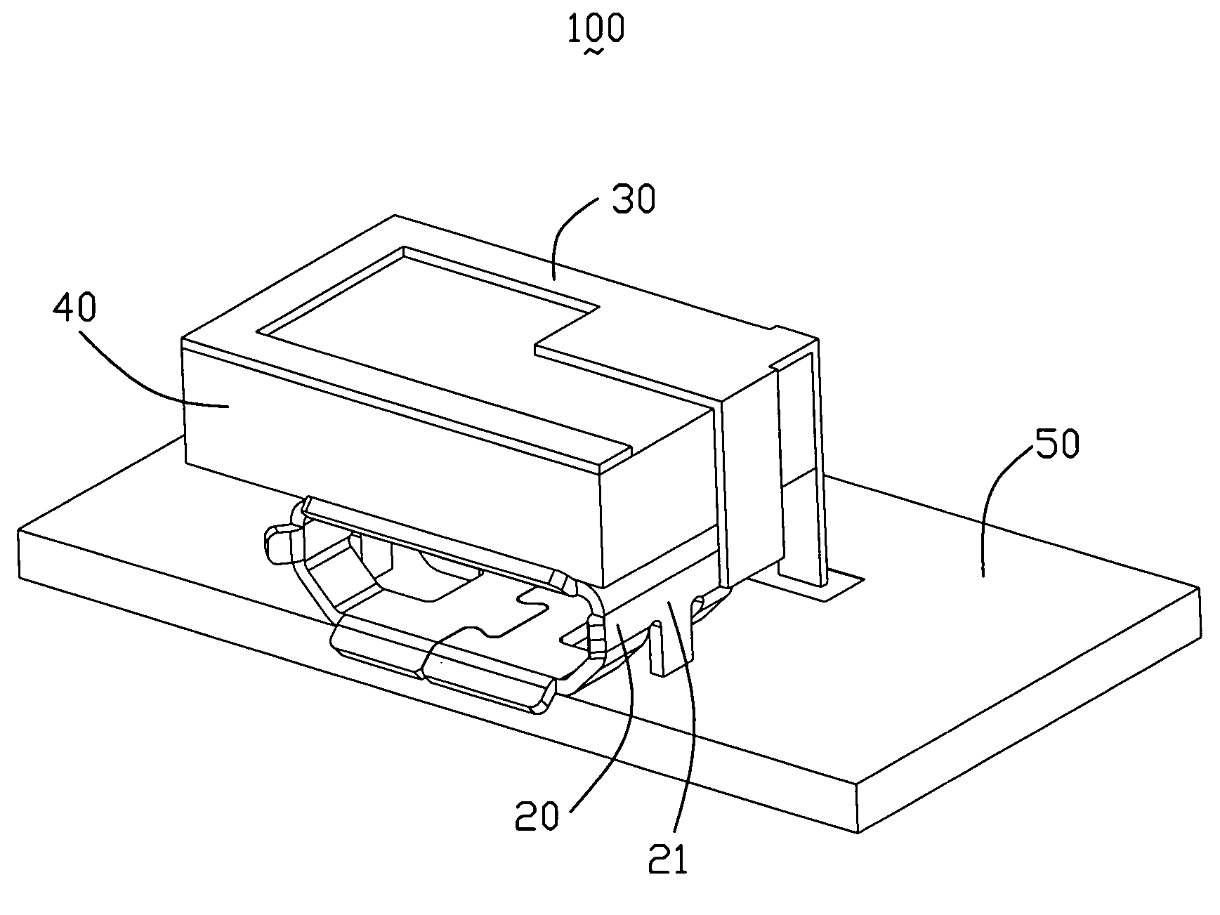
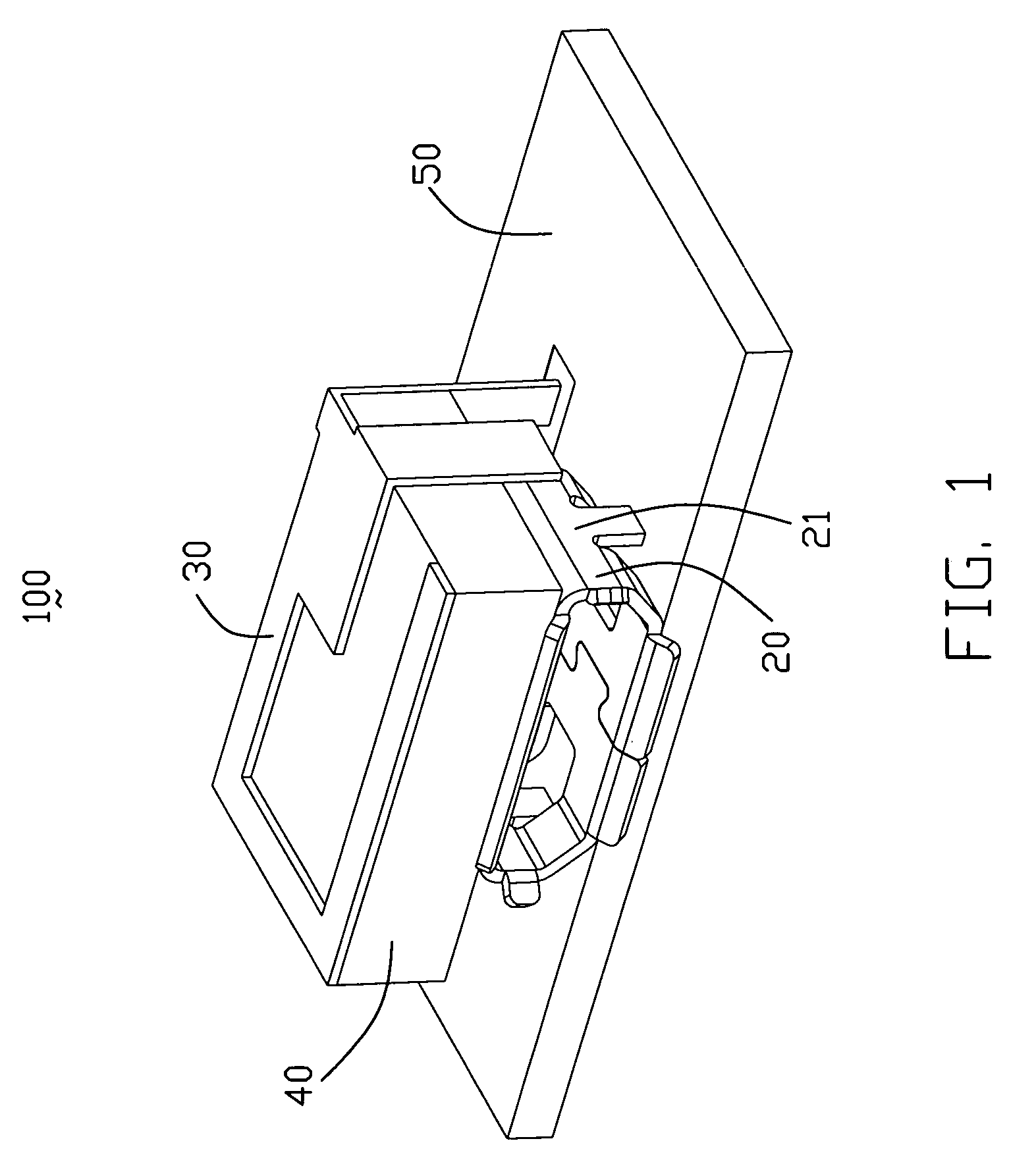
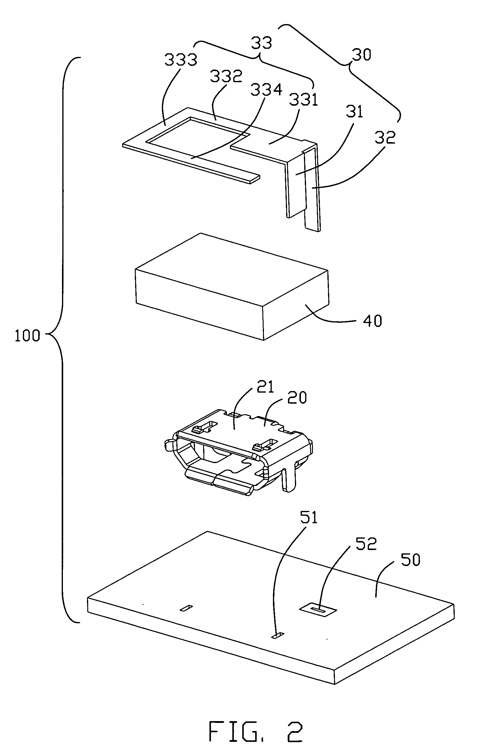
[0016]Referring to FIGS. 1-3, an electrical connector assembly 100 with antenna function in accordance with a preferred embodiment of the present invention comprises a micro USB electrical connector 20, a metal patch 30, an insulating support element 40, and a PCB 50.

[0017]The USB electrical connector 20 comprises an insulating body (not shown), several contacts (not shown) received in the insulating body, and a metal shell 21 covering the insulating body. The metal shell 21 comprises a welding element 211 extending vertically and downwardly from a bottom surface of the metal shell 21.

[0018]The metal patch 30 connects to the metal shell 21 of the USB connector 20. Accordingly, the metal patch 30 and the metal shell form an antenna that serves as a medium for transmission and reception of electromagnetic signals. The metal patch 30 comprises a connecting element 31 lying in a first plane a...


PUM


Abstract

An electrical connector assembly (100) with antenna function comprising: an electrical connector (20) comprising a metal shell (21); a metal patch (30) connecting to the metal shell (20) and comprising a radiating element (33) and a connecting element (31); an insulating support element (40) locating between the radiating element and the metal shell; the radiating element locating on top of the metal shell; the connecting element connecting to the metal shell that serve as a grounding element; the radiating element, the connecting element, and the metal shell forming an antenna that serves as a medium for transmission and reception of electromagnetic signals.

Description

BACKGROUND OF THE INVENTION[0001]1. Field of the Invention[0002]The present invention relates to an electrical connector assembly, and more particularly to electrical connector assembly having antenna function.[0003]2. Description of Prior Art[0004]Personal computer technologies have been embraced in many portable electronics devices including: cellular telephones, personal data assistants (PDAs), laptop computers, MP3 players, pen-drives, digital video cameras, as well as other mobile devices. Many of the portable electronic devices can be configured to operate with various peripheral devices such as a computer mouse, a computer writing tablet, a digital camera, as well as others. Moreover, many of the portable electronic devices are also configured to interface with personal computers through a standard interface.[0005]The need for standardization in computer related interfaces, as well as the need for high-speed communication interfaces has lead to the development of the universa...

Claims


Application Information

Patent Timeline
IPC IPC(8): H01Q1/50H01Q1/38
CPCH01Q1/1207H01Q1/38H01Q1/44H01Q9/0407H01R13/6633H01R13/6658H01R2201/02H01R2107/00H01R24/62H01R13/6594H01R12/712
Inventor TAI, LUNG-SHENGSU, WEN-FONGTSENG, HSIEH-SHENG
Owner HON HAI PRECISION IND CO LTD
Why Eureka
Try Eureka