Method for Flight Control of a Plurality of Aircraft Flying in Formation

a technology of flight control and aircraft, applied in the direction of traffic control systems, position/direction control, instruments, etc., can solve the problem that the method on which the system is based is not very suitable for a use during highly dynamic flying maneuvers

Inactive Publication Date: 2010-07-01
EADS DEUT GMBH
View PDF8 Cites 56 Cited by
  • Summary
  • Abstract
  • Description
  • Claims
  • Application Information

AI Technical Summary

Benefits of technology

[0010]One object of the invention is to provide a method of the above-mentioned type, in whi

Problems solved by technology

The problem of an automated aircraft close-formation flight concerns the determination of the trajectory of a following aircraft as well as its positi

Method used


Image

  • Method for Flight Control of a Plurality of Aircraft Flying in Formation
  • Method for Flight Control of a Plurality of Aircraft Flying in Formation
  • Method for Flight Control of a Plurality of Aircraft Flying in Formation

Examples


Embodiment Construction

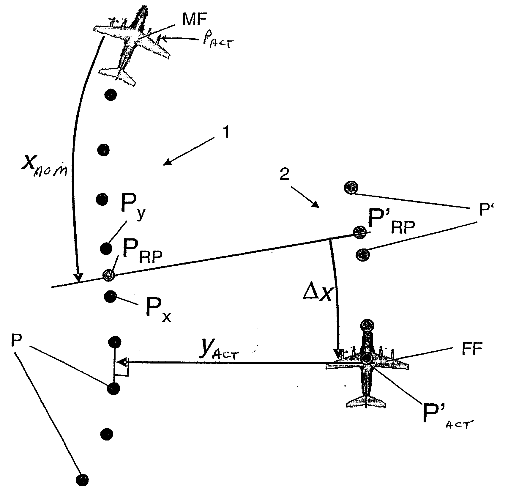
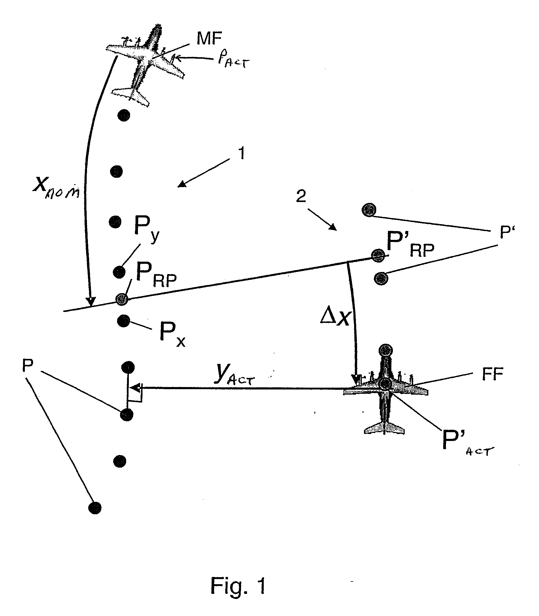
[0034]In a planar representation, FIG. 1 shows a trajectory 1 of a lead aircraft MF with support points P, as well as an estimated trajectory 2 of a following aircraft FF with support points P′ that were calculated based on the support points P on the trajectory 1 of the lead aircraft.

[0035]Reference symbol Xnom indicates the predetermined relative longitudinal distance between the lead aircraft MF and the following aircraft FF. The lateral actual distance between the lead aircraft MF and the following aircraft FF is marked yact. (The predetermined vertical distance is not shown.) The longitudinal nominal distance Xnom is expediently determined before the aircraft form a formation, for example, by the pilots. A corresponding situation applies to a predetermined vertical and lateral nominal distance. The distances can be indicated either in time units or distance units.

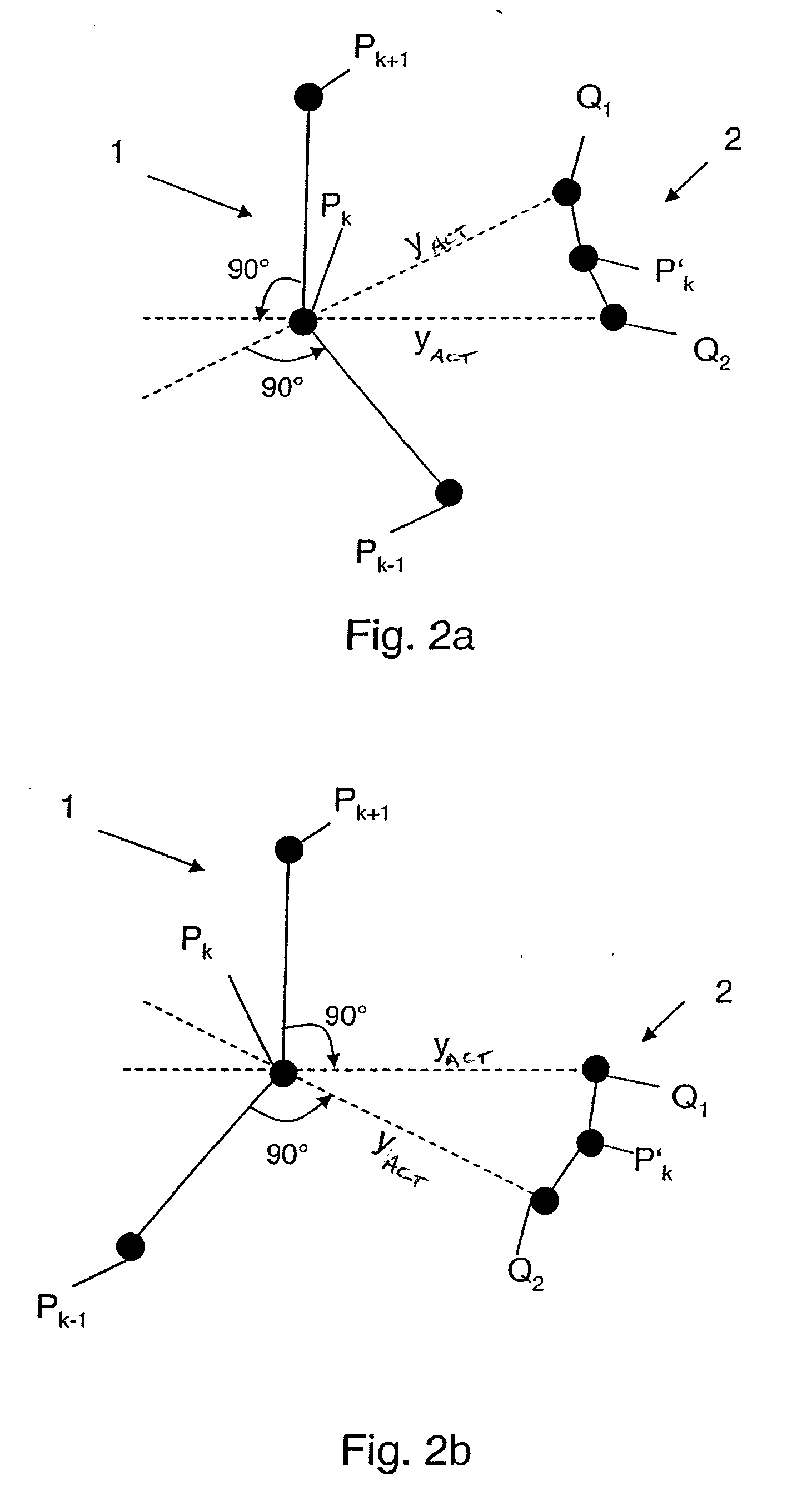
[0036]For the determination of a support point PRP for the reference point on the trajectory of the lead aircraft, t...


PUM


Abstract

In a method for the flight control of a plurality of aircraft flying in formation with respect to one another, correction signals are generated for an autopilot system or a command display in order to allow one or more following aircraft within the formation to follow a lead aircraft in the formation in a predeterminable relative position. A nominal trajectory of the following aircraft, parallel to the trajectory (1) of the lead aircraft, is calculated at each instantaneous position P′act of the following aircraft, which trajectory runs through the instantaneous actual position P′act and a reference point P′RP. (The reference point P′RP is the projection of a point PRP, which is separated by the longitudinal nominal distance xnom between the lead aircraft and the following aircraft, on the trajectory of the lead aircraft, taking into account the lateral and vertical actual distances yact and zact between the trajectory of the lead aircraft and that of the following aircraft. The trajectory of the following aircraft is calculated taking into account the lateral actual distance yact from the trajectory of the lead aircraft by determining support points P′ on the trajectory of the following aircraft which have the same time coordinates as the corresponding support points on the trajectory of the lead aircraft. The correction signals are determined by i) measuring the longitudinal, lateral and vertical actual distances xact, vact and zact between the trajectory of the lead aircraft and that of the following aircraft at the instantaneous position P′act of the following aircraft, ii) calculating the longitudinal deviation Δx, the vertical deviation Δz and the lateral deviation Δy of the instantaneous actual position P′act and of the nominal position P′nom of the following aircraft from the respective nominal values xnom, znom, ynom and the measured actual values xact, zact, yact, iii) calculating the nominal speed and the nominal acceleration of the following aircraft at the point P′RP, and iv) calculating the nominal curvature, the nominal climbing rate and the nominal curvature angle Ψ of the trajectory of the following aircraft at the instantaneous position P′act of the following aircraft.

Description

[0001]This application is a national stage of PCT International Application No. PCT / DE2006 / 001354, filed Aug. 3, 2006, which claims priority under 35 U.S.C. §119 to German Patent Application No. 10 2005 038 017.4, filed Aug. 9, 2005, the entire disclosure of which is herein expressly incorporated by reference.BACKGROUND AND SUMMARY OF THE INVENTION[0002]The invention relates to a method for the flight control of a plurality of aircraft flying in formation.[0003]Flight control in formation flights is discussed, for example, in Published U.S. Patent No. US 2005 / 0165516 A1 and U.S. Pat. No. 6,587,757 B2, which relates to a coordinated flight of a plurality of aircraft. Automatic flight control in a formation flight requires that reference signals be supplied to the flight control system of a following aircraft in order to keep the following aircraft in a desired position relative to the lead aircraft. The reference signals must sort out external disturbances, such as wind gusts or prev...

Claims


Application Information

Patent Timeline
IPC IPC(8): G05D1/00
CPCG08G5/0052G05D1/104
Inventor SOIJER, MARCO WILLEMZOBERBIER, MANFREDGOERKE, ROLAND
Owner EADS DEUT GMBH
Why Eureka
Try Eureka