Joint mechanism for robot

a joint mechanism and robot technology, applied in the direction of rod connection, program-controlled manipulator, fastening means, etc., can solve the problems of affecting the performance of the robotic machine, oil, dirt, liquid substances, etc., and the joints of the rotary unit can easily collect contaminants such as oil, dirt,

Inactive Publication Date: 2010-07-15
HON HAI PRECISION IND CO LTD
View PDF12 Cites 133 Cited by
  • Summary
  • Abstract
  • Description
  • Claims
  • Application Information

AI Technical Summary

Problems solved by technology

Industrial robotic machines are used to carry out repetitious, precise, burdensome, and even dangerous tasks, such as welding and painting of components.
However, when the robotic machine runs under poor conditions, for example in an environment contaminated with grease and dirt, the adjoining surfaces of the rotary units easily collect contaminants such as oil, dirt, and liquid substances.
Thus, contaminants can easily enter the rotary units when the rotary joints rotate, and impair internal components of the robotic machine, as a result, affecting the performance of the robotic machine.

Method used


Image

  • Joint mechanism for robot
  • Joint mechanism for robot
  • Joint mechanism for robot

Examples


Embodiment Construction

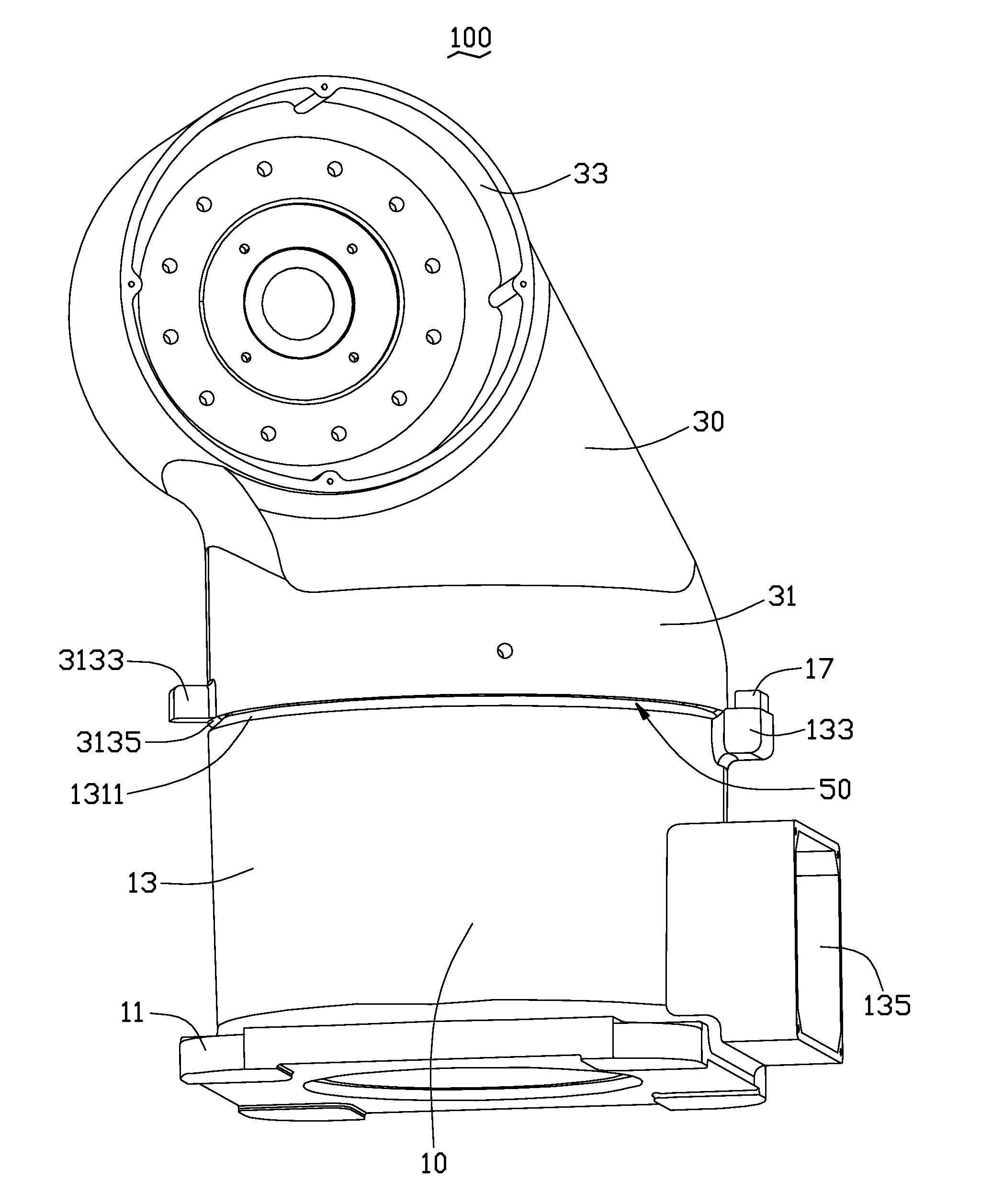
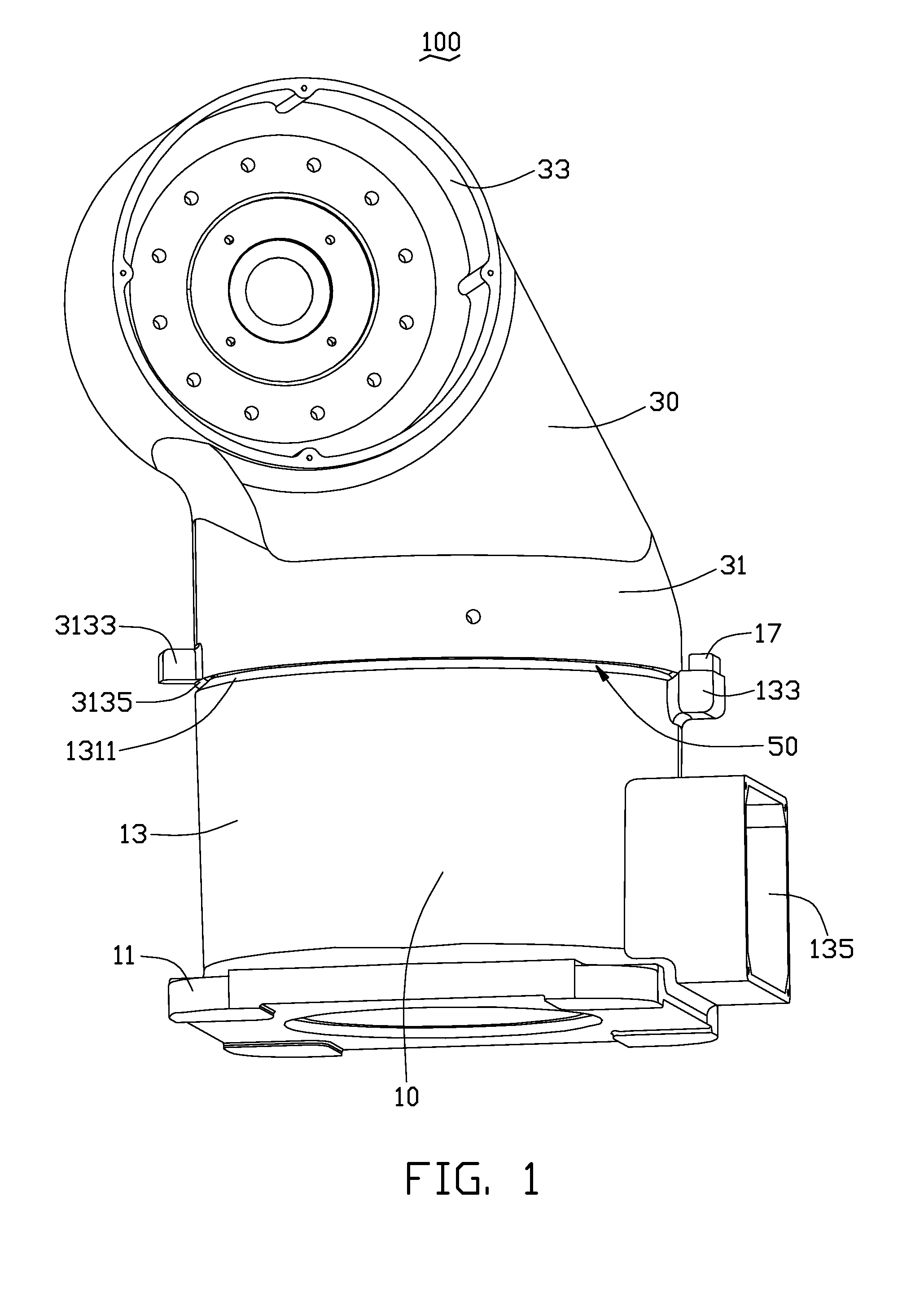
[0012]Referring to FIG. 1, an embodiment of a joint mechanism 100 includes first rotary unit 10 and a second rotary unit 30 rotatable relative to the first rotary unit 10.

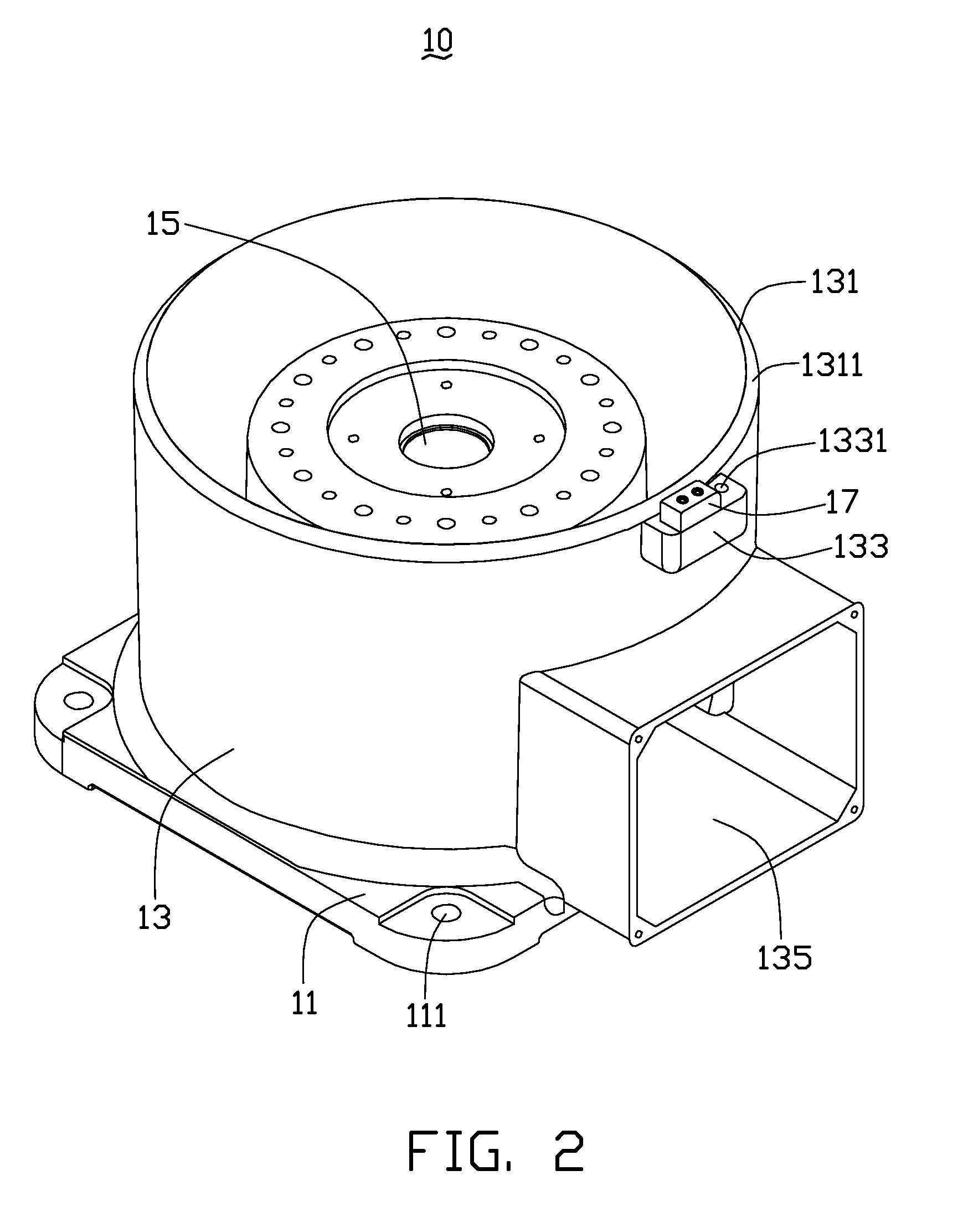
[0013]Referring to FIG. 2, the first rotary unit 10 includes a base 11, a housing 13 extending from the base 11, a first mounting portion 15 extending from the base 11, and a limiting portion 17.

[0014]The base 11 defines at least one mounting hole 111.

[0015]The housing 13 may be a cylinder extending from a surface of the base 11. The housing 13 includes a first joining end 131 defining an opening (not labeled), a first positioning portion 133, and a wire receptacle 135. The first joining end 131 is at an end of the housing 13 opposite to the base 11. The first joining end 131 is circular in shape so as to rotatably connect to the second rotary unit 30. The first joining end 131 defines a first chamfered rim 1311. A chamfered angle of the first chamfered rim 1311 may be in a range of about 30˜60 degrees, and is 45 d...


PUM


Abstract

A joint mechanism includes a first rotary unit and a second rotary unit. The first rotary unit includes a base and a first joining end. The first joining end defines a first chamfered rim. The second rotary unit includes a second joining end to join to the first joining end. The second joining end defines a second chamfered rim. The first chamfered rim and the second chamfered rim cooperatively form a slanted groove. The groove communicates with an outside of the first and second rotary units and has an opening facing the base.

Description

BACKGROUND[0001]1. Technical Field[0002]The present disclosure generally relates to joint mechanism and, particularly, to a joint mechanism for robots.[0003]2. Description of Related Art[0004]Industrial robotic machines are used to carry out repetitious, precise, burdensome, and even dangerous tasks, such as welding and painting of components. Therefore, industrial robotic machines are popular in the many fields such as mechanical manufacturing, metallurgy, and atomic domain. The robotic machine usually has a plurality of rotary joints to perform complex movements. Two rotary units having rotary joints are usually connected together and rotate relative to each other. A gap exists between the rotary units because there needs to be a space that allows the rotary units to rotate relative to each other.[0005]However, when the robotic machine runs under poor conditions, for example in an environment contaminated with grease and dirt, the adjoining surfaces of the rotary units easily coll...

Claims


Application Information

Patent Timeline
Patent Type & Authority Applications(United States)
IPC IPC(8): F16B7/00
CPCB25J9/101Y10T403/32549Y10T403/32983B25J17/025
Inventor DAY, CHIA-PENGSHIH, CHOU-CHEN
Owner HON HAI PRECISION IND CO LTD
Why Eureka
Try Eureka