Structural Attachment System for Transition Duct Outlet

Inactive Publication Date: 2010-07-22
SIEMENS ENERGY INC
View PDF40 Cites 59 Cited by
  • Summary
  • Abstract
  • Description
  • Claims
  • Application Information

AI Technical Summary

Benefits of technology

[0016]The member has an outer flange at a first end of the step over portion and an inner flange at a second end of the step over portion. The outer flange is attached to the radially outer support structure by, for example, fasteners. The inner flange is attached to the radially inner support structure, such as by bolts. The ste

Problems solved by technology

These relative movements can produce high stresses within the first row of vanes.
In addition, these relative movements can cause ID-to-OD rocking of the vane between the inner platform element of the vane and the transition duct from the combustor, potentially resulting in substantial gas leakage and loss of efficiency due to the large relative displacement.
However, there is not enough space for a substantial support member because any support member must be circumferentially narrow to fit in the li

Method used


Image

  • Structural Attachment System for Transition Duct Outlet
  • Structural Attachment System for Transition Duct Outlet
  • Structural Attachment System for Transition Duct Outlet

Examples


Embodiment Construction

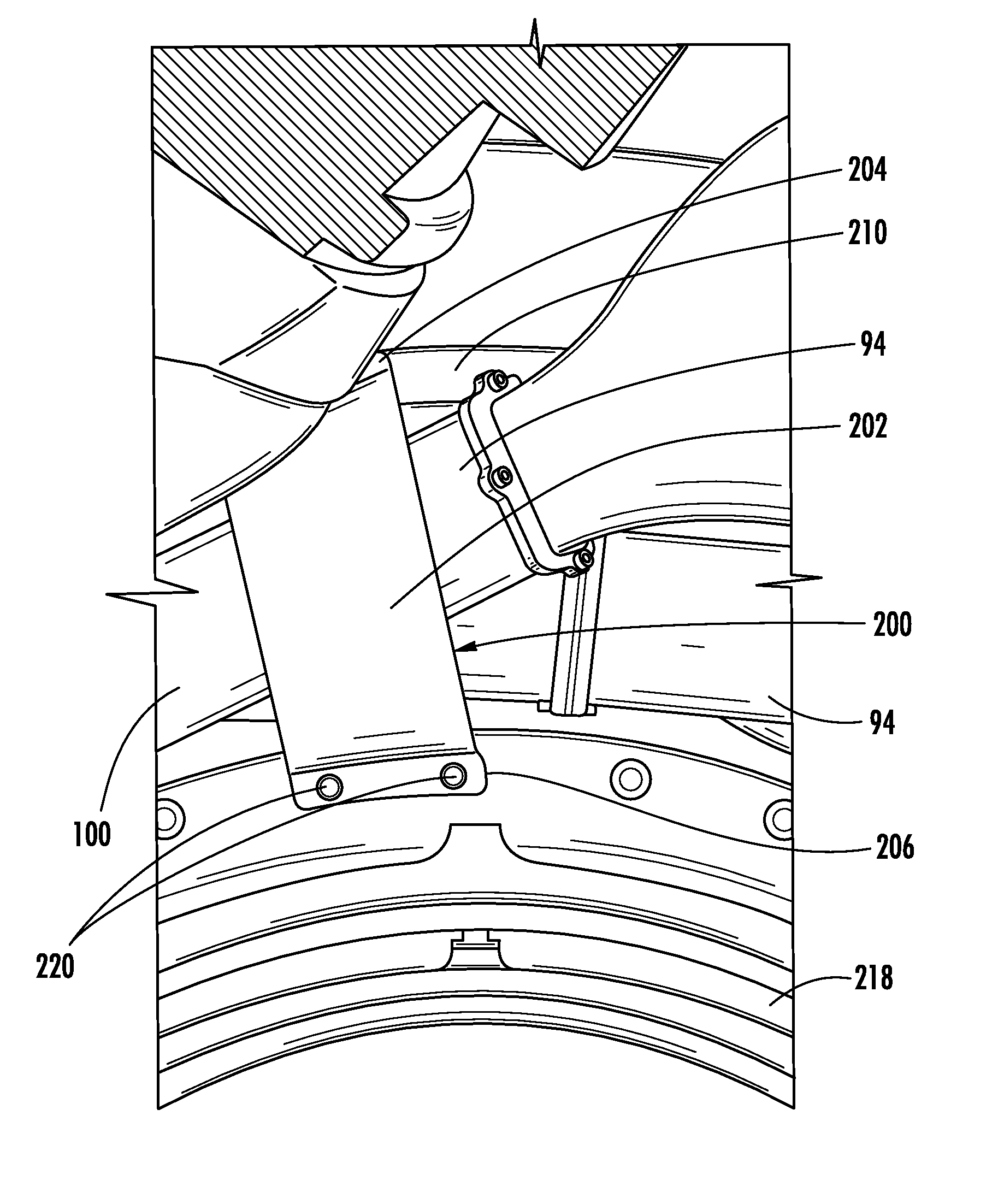
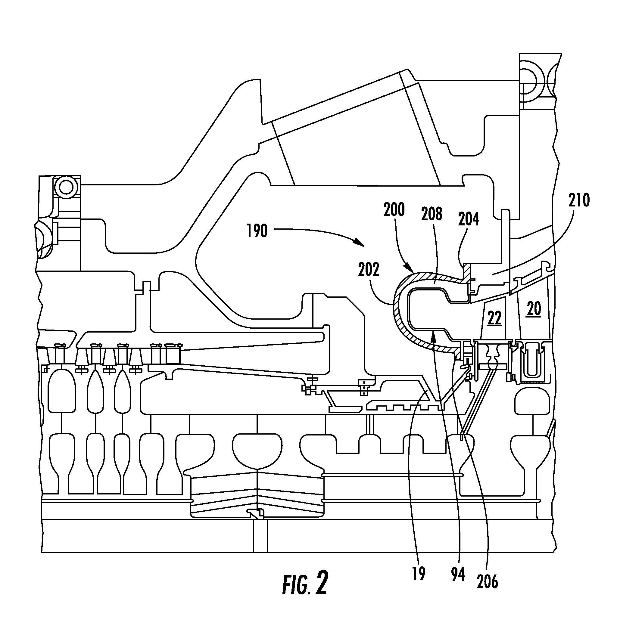
[0028]Aspects of the present invention relate to a structural attachment system for the outlet of a transition duct. Embodiments of the invention will be explained in connection with transition ducts that supply combustion gases with high tangential velocity directly to a first row of blades, but the detailed description is intended only as exemplary. Embodiments of the invention are shown in FIGS. 2-10, but aspects of the invention are not limited to the illustrated structure or application.

[0029]A system according to aspects of the invention includes a transition outlet structural attachment member 200. The structural attachment member 200 can have a step over portion 202 with an outer flange 204 at one end thereof and an inner flange 206 at the other end thereof. The step over portion 202 can project away from the inner and outer flanges 204, 206 and can define an open area 208. The step over portion 202 can have any suitable configuration. For instance, the step over portion 202...


PUM


Abstract

A structural attachment system for the outlet of a transition duct includes a structural attachment member that has a step over portion with an outer flange at one end thereof and an inner flange at the other end thereof. The step over portion can project away from the inner and outer flanges and can define an open area. The step over portion can have a cross-section that is generally u-shaped, v-shaped, c-shaped, semi-circular, semi-oval, parabolic, or bowed. A portion of the outlet of a transition duct is received within the step over portion of the structural attachment member. Because of such arrangement, the structural attachment member is not constrained circumferentially to fitting in between two neighboring transition ducts. The structural attachment member can manage the thermal displacements that can occur between the transitions, rotor shaft cover and first row of blades during transient engine operation.

Description

FIELD OF THE INVENTION[0001]The invention relates in general to turbine engines and, more specifically, to a support system for transition ducts.BACKGROUND OF THE INVENTION[0002]Referring to FIG. 1, a turbine engine 10 can generally include a compressor section 12, a combustor section 14 and a turbine section 16. A centrally disposed rotor 18 can extend through the three sections. Portions of the rotor 18 can be protected by a rotor shaft cover 19.[0003]The turbine section 16 can include alternating rows of vanes 20 and rotating blades 22. Each row of blades 22 can include a plurality of airfoils attached to a disc 24 provided on the rotor 18. The rotor 18 can include a plurality of axially-spaced discs 24. The blades 22 can extend radially outward from the discs 24.[0004]Each row of vanes 20 can be formed by attaching a plurality of vanes 20 to the stationary support structure in the turbine section 16. For instance, the vanes 20 can be mounted on a vane carrier 26 that is attached...

Claims


Application Information

Patent Timeline
IPC IPC(8): F02C7/20
CPCF01D9/023F02C3/14F05B2260/301F23R2900/00005F05D2260/941F23R3/425F23R3/60F05D2260/94
Inventor CHARRON, RICHARD
Owner SIEMENS ENERGY INC
Why Eureka
Try Eureka