Display Device

a display panel and circuit board technology, applied in the direction of electrical equipment, instruments, cooling/ventilation/heating modifications, etc., can solve the problems of temperature in the casing increases, display panel or circuit board trouble,

Active Publication Date: 2010-07-22
SANYO ELECTRIC CO LTD
View PDF2 Cites 70 Cited by
  • Summary
  • Abstract
  • Description
  • Claims
  • Application Information

AI Technical Summary

Benefits of technology

[0012]A display device of the present invention comprises a display panel, a cooling unit cooling air in a casing containing the display panel, a fan unit generating an air flow in the casing, and a control unit controlling the cooling unit and the fan unit, and when the control unit deactivates the cooling unit, the control unit also deactivates the fan unit.

Problems solved by technology

Therefore, when displays are permanently installed outdoors, and a trouble may occur in the display panel or the circuit board because the panel or the circuit board is disposed to rainstorm etc.
However, when the display panel and the circuit board are arranged in a sealed casing, heat generated from the display panel or the circuit board stays inside the casing, and the temperature in the casing increases.
Accordingly a trouble may possibly occur in the display panel or the circuit board.
Further, when these displays are installed outdoors, a temperature of the image display screen of the display panel increases because of the sunlight.
As a result, a trouble may occur in the display panel, for example, a “blackout”.
As a result, dew condensation occurs on a rear surface of the glass plate, and a viewability of the image display screen of the display panel is deteriorated.

Method used


Image

  • Display Device
  • Display Device
  • Display Device

Examples


first embodiment

1. First Embodiment

(The Structure of the Display Device)

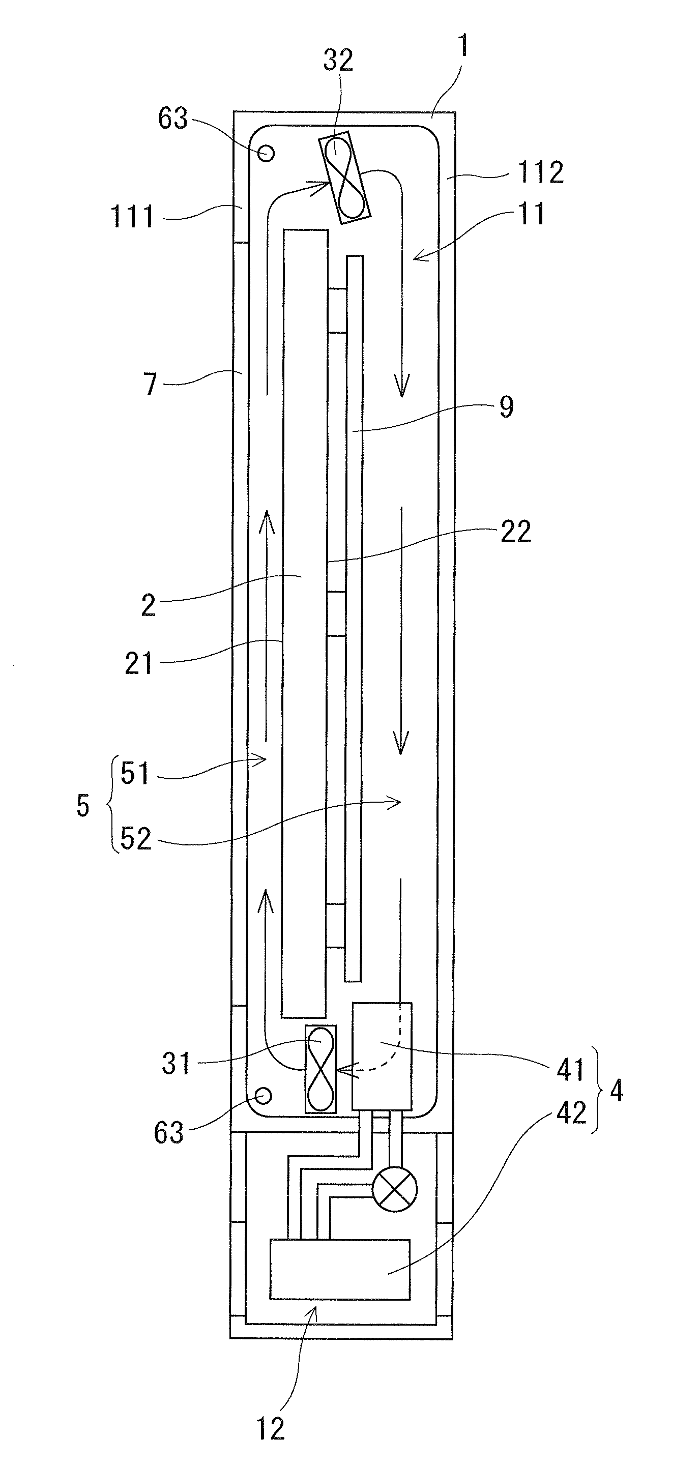
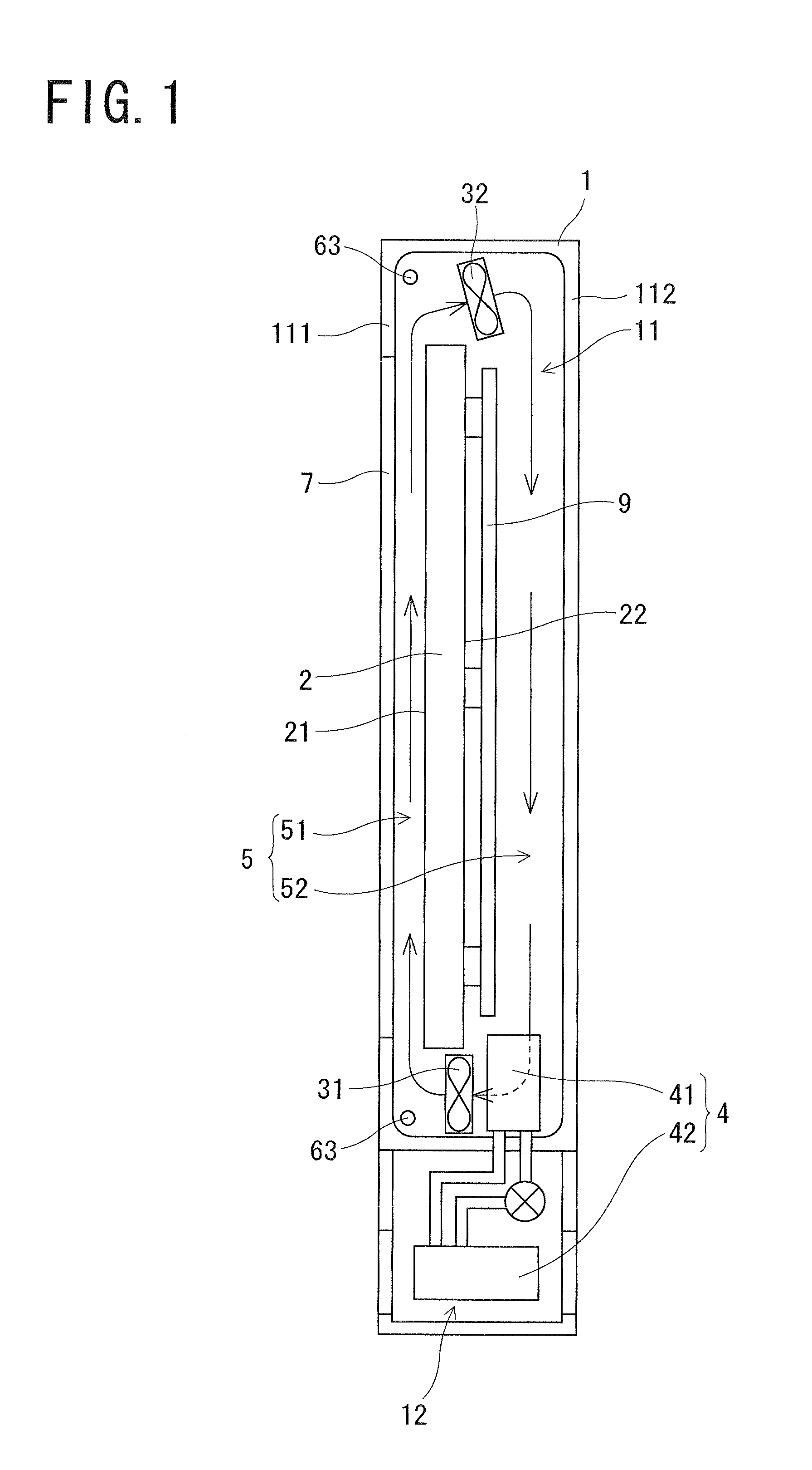
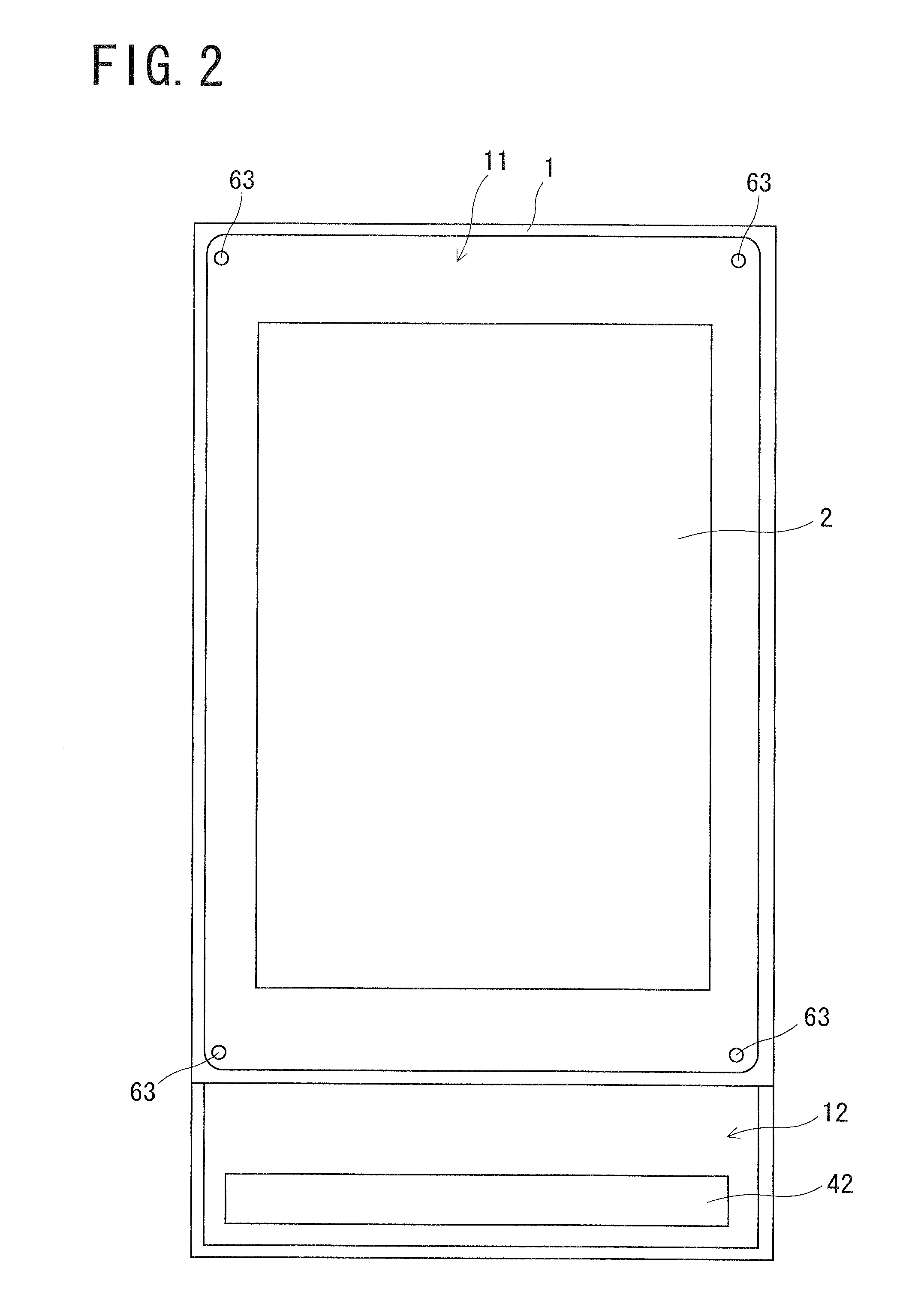
[0024]As shown in FIG. 1, a display device according to a first embodiment of the present invention comprises a casing 1 having a waterproof structure. Inside the casing 1, defined are an accommodation room 11, and a second accommodation room 12 which is under the accommodation room 11.

[0025]Inside the accommodation room 11, provided are a liquid crystal display panel 2 comprising an image display screen 21, and a circuit board 9 for controlling the display device. The liquid crystal display panel 2 is arranged with the image display screen 21 thereof facing a front surface side of the casing 1, while the circuit board 9 is arranged on a rear surface 22 of the liquid crystal display panel 2.

[0026]The accommodation room 11 includes a front surface wall 111 a part of which is formed by a glass plate 7. The glass plate 7 faces the image display screen. It is thereby possible to view the image display screen 21 from the front surfa...

second embodiment

2. Second Embodiment

(The Structure of the Display Device)

[0070]As shown in FIG. 5, a display device according to a second embodiment further comprises a glass temperature sensor for measuring a temperature Ts1 of the glass plate 7 compared with the display device shown in FIG. 1. The sensor is arranged on a rear surface of the glass plate 7 where the air cooled by the cooling device 4 is blown.

[0071]The air cooled by the cooling device 4 flows from the rear surface side flow passage part 52 into the front surface side flow passage part 51 through the space below the liquid crystal display panel 2. Therefore, a rear surface of the glass plate 7 tends to be cooled in its lower area. In this embodiment, the glass temperature sensor 61 is arranged in this lower area, as shown in FIG. 5.

[0072]The number of glass temperature sensors 61 arranged on the glass plate 7 is not limited to one, and may be two or more.

(Controls Executed in Display Device)

[0073]FIG. 6 is a block diagram showing a ...


PUM

PropertyMeasurementUnit
timeaaaaaaaaaa
temperatureaaaaaaaaaa
Structureaaaaaaaaaa

Abstract

A display device comprises a display panel, a cooling unit cooling air in a casing containing the display panel, a fan unit generating an air flow in the casing, and a control unit controlling the cooling unit and the fan unit, and when the control unit deactivates the cooling unit, the control unit also deactivates the fan unit.

Description

[0001]This application which claims priority under 35 U.S.C. §119 from the Japanese patent application Number 2009-008757 is incorporated by reference herein.BACKGROUND OF THE INVENTION[0002]1. Field of the Invention[0003]The present invention relates to a display device which can be installed outdoors.[0004]2. Description of Related Art[0005]Conventionally, flat type displays such as a liquid crystal display are widely used. Most of the conventional flat type displays are designed for indoor installations, and the measures to protect them from the environmental condition such as a rainstorm, dust etc. are not taken. Therefore, when displays are permanently installed outdoors, and a trouble may occur in the display panel or the circuit board because the panel or the circuit board is disposed to rainstorm etc.[0006]In view of this, it was considered to arrange the display panel and the circuit board in a sealed casing in order to protect them.[0007]However, when the display panel and...

Claims


Application Information

Patent Timeline
Patent Type & Authority Applications(United States)
IPC IPC(8): G02F1/1333
CPCG02F1/133385H05K7/20972H05K7/2099
Inventor YOSHIDA, TOMONORISATO, HIDENORIUCHIDA, HIROYUKITAKAHASHI, SHOHEIFUKAGAWA, RYUJI
Owner SANYO ELECTRIC CO LTD
Why Eureka
Try Eureka