Fluidic rim seal system for turbine engines

a technology of turbine engines and rim seals, which is applied in the direction of liquid fuel engines, machines/engines, mechanical equipment, etc., can solve the problems of high demand for air, inefficient air distribution, and inefficient arrangement, and achieve the effect of minimizing the ingestion of hot gas between the disk cover plate and the stationary turbine componen

Inactive Publication Date: 2010-07-22
SIEMENS ENERGY INC
View PDF21 Cites 39 Cited by
  • Summary
  • Abstract
  • Description
  • Claims
  • Application Information

AI Technical Summary

Benefits of technology

[0013]The passage can have an inlet in fluid communication with a coolant source. Thus, coolant supplied to the passage can exit at the outlet and impinge on the groove such that an fluid barrier is formed. As a result, hot gas ingestion between the disk cover plate and the stationary turbine component can be minimized.

Problems solved by technology

As a result, inefficient distribution of the air occurs, as the majority of the air will naturally tend to the low pressure of the aft cavity 34 and will be able to do so because of the gap 38 between the u-ring 22 and the rotor disks 12.
Such an inefficient arrangement keeps the demand for the air at a high level, which prevents the beneficial use of such air in other areas.
In some cases, hot gas ingestion into the forward cavity 32 is a result of such inefficient distribution of the purge air.
However, this alone is an insufficient barrier to hot gas ingestion.

Method used


Image

  • Fluidic rim seal system for turbine engines
  • Fluidic rim seal system for turbine engines
  • Fluidic rim seal system for turbine engines

Examples


Embodiment Construction

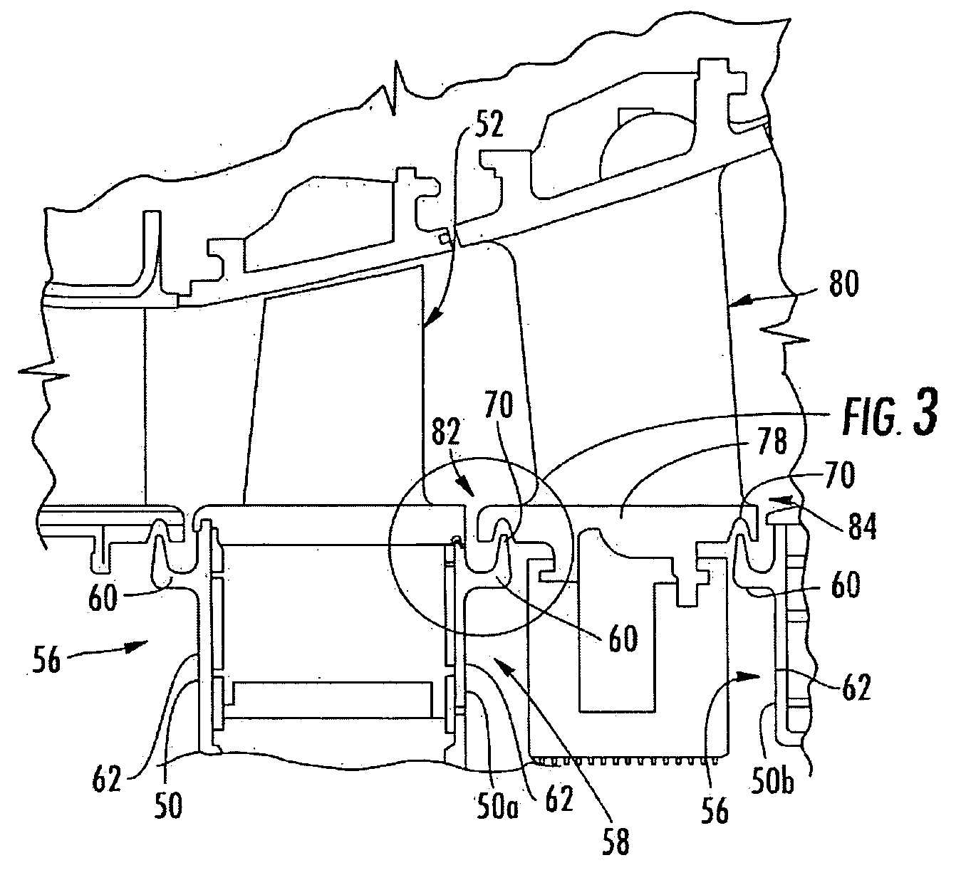
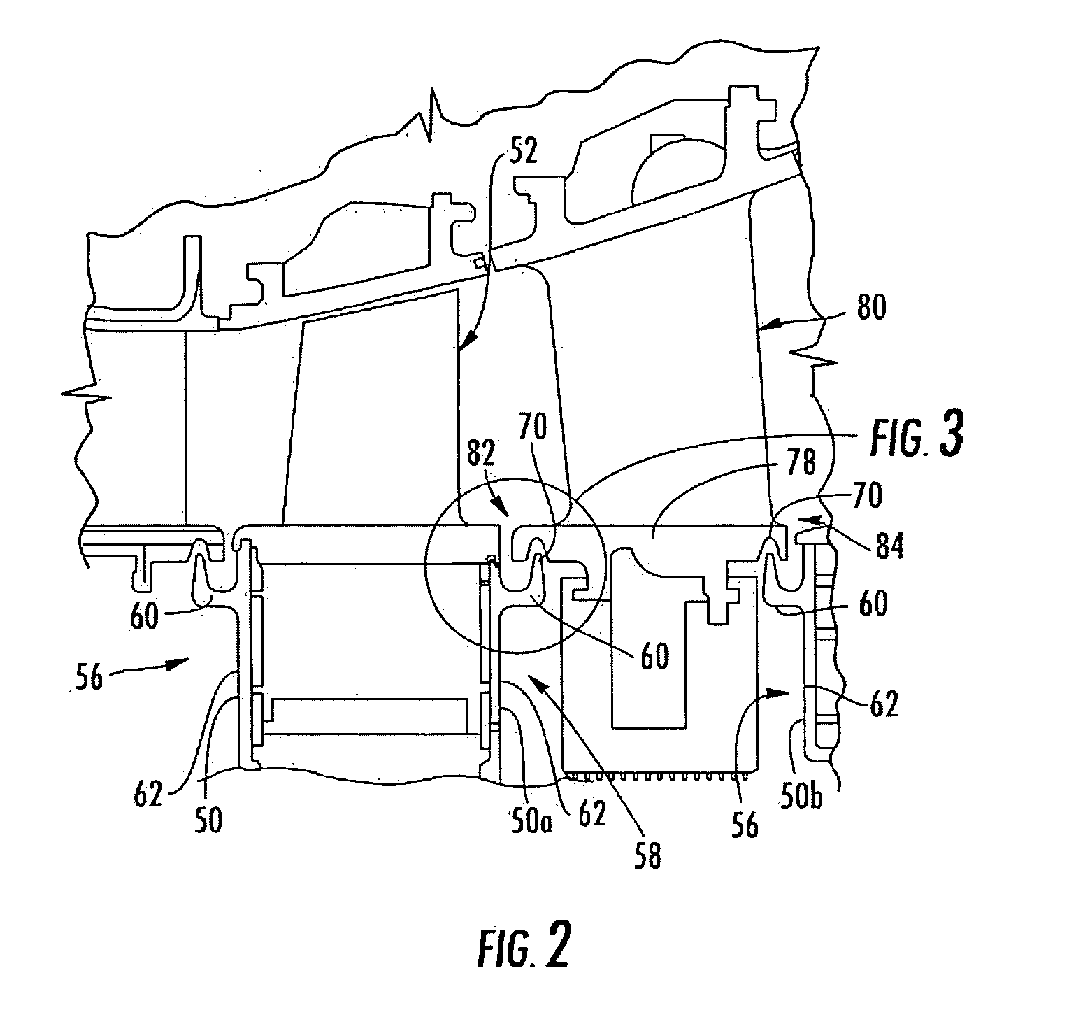
[0022]A system and method according to aspects of the present invention can reduce total purge air flow demand for turbine rim cavities and / or can minimize hot gas ingestion into a turbine rim cavity. Embodiments of the invention will be explained in connection with one possible arrangement, but the detailed description is intended only as exemplary. Embodiments of the invention are shown in FIGS. 2-3, but aspects of the invention are not limited to the illustrated structure or application.

[0023]Embodiments of the invention can be applied in various interfaces between stationary and rotatable components in a turbine engine. In one embodiment, the rotatable component can be a blade cover plate 50, which can be secured to one or more of the structures associated with a row of blades 52, such as the rotor disk and / or portions of blades themselves. Such securing can be achieved in any suitable manner, including, for example, by mechanical engagement. The blade cover plate 50 can be prov...


PUM


Abstract

A fluidic rim seal system can be provided between a neighboring stationary and rotatable components in the turbine section of a turbine engine. For instance, the stationary component can be an inner shroud associated with a vane. The inner shroud can include a groove that extends circumferentially about the shroud. The rotatable component can be a blade cover plate. The blade cover plate can include a protrusion that culminates at a tip. One or more passages can extend through the protrusion. The passages can have an inlet in fluid communication with a coolant source and an outlet at the tip. A tip region of the protrusion is received in the groove. During engine operation, an air barrier is formed in the groove by the air discharging from the outlet. This air also provides cooling to the protrusion as well as a portion of the inner shroud.

Description

FIELD OF THE INVENTION[0001]The invention relates in general to turbine engines and, more specifically, to a system and method for sealing between stationary and rotating turbine components.BACKGROUND OF THE INVENTION[0002]Referring to FIG. 1, the turbine section 10 of a turbine engine includes a plurality of disks 12 provided on a rotor (not shown). The discs 12 are axially spaced along the rotor. A plurality of blades 14 are mounted on each disk 12 to form a row of blades 14. The blades 14 are circumferentially arrayed about each disk 12 and extend radially outward therefrom.[0003]The rows of blades 14 alternate with rows of stationary airfoils or vanes 16. The vanes 16 are attached at one end to a vane carrier 18 and extend radially inward therefrom to a radially inner end, which can include an inner shroud 20. Additional structures can be attached to the inner shroud 20, including, for example, a u-shaped ring 22. Labyrinth seals 23 can be attached to the u-shaped ring 22 as wel...

Claims


Application Information

Patent Timeline
Patent Type & Authority Applications(United States)
IPC IPC(8): F02C7/28
CPCF01D11/04F01D25/12F02C7/12F02C7/28F05D2240/55F05D2260/20
Inventor LIANG, GEORGE
Owner SIEMENS ENERGY INC
Why Eureka
Try Eureka