Stator rim for a turbine engine

a technology of turbine engine and rim, which is applied in the direction of stators, machines/engines, mechanical equipment, etc., can solve problems such as reducing the efficiency of the system

Active Publication Date: 2017-07-13
GENERAL ELECTRIC CO
View PDF3 Cites 3 Cited by
  • Summary
  • Abstract
  • Description
  • Claims
  • Application Information

AI Technical Summary

Benefits of technology

[0003]In a first aspect, a structure for a gas turbine engine includes a stator having an end wall and a discourager defining a channel therebetween. The structure also has the end wall adjacent to a hot gas flow and the discourager adjacent to a purge flow. A rotor having an angel wing extends into th

Problems solved by technology

The compressor vanes are disposed with seals, limiting airflow leakage to u

Method used


Image

  • Stator rim for a turbine engine
  • Stator rim for a turbine engine
  • Stator rim for a turbine engine

Examples


Embodiment Construction

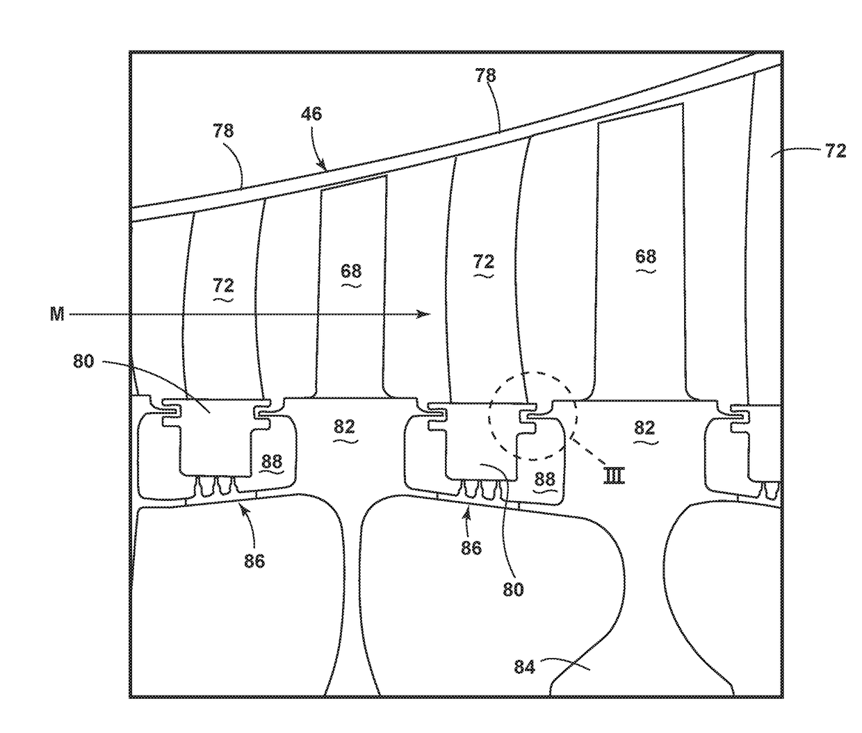
[0011]The described embodiments of the present invention are directed to a high pressure turbine, and in particular to preventing hot gas ingestion into a cavity between a turbine stator and rotor. For purposes of illustration, the present invention will be described with respect to the turbine for an aircraft gas turbine engine. It will be understood, however, that the invention is not so limited and can have general applicability in non-aircraft applications, such as other mobile applications and non-mobile industrial, commercial, and residential applications.

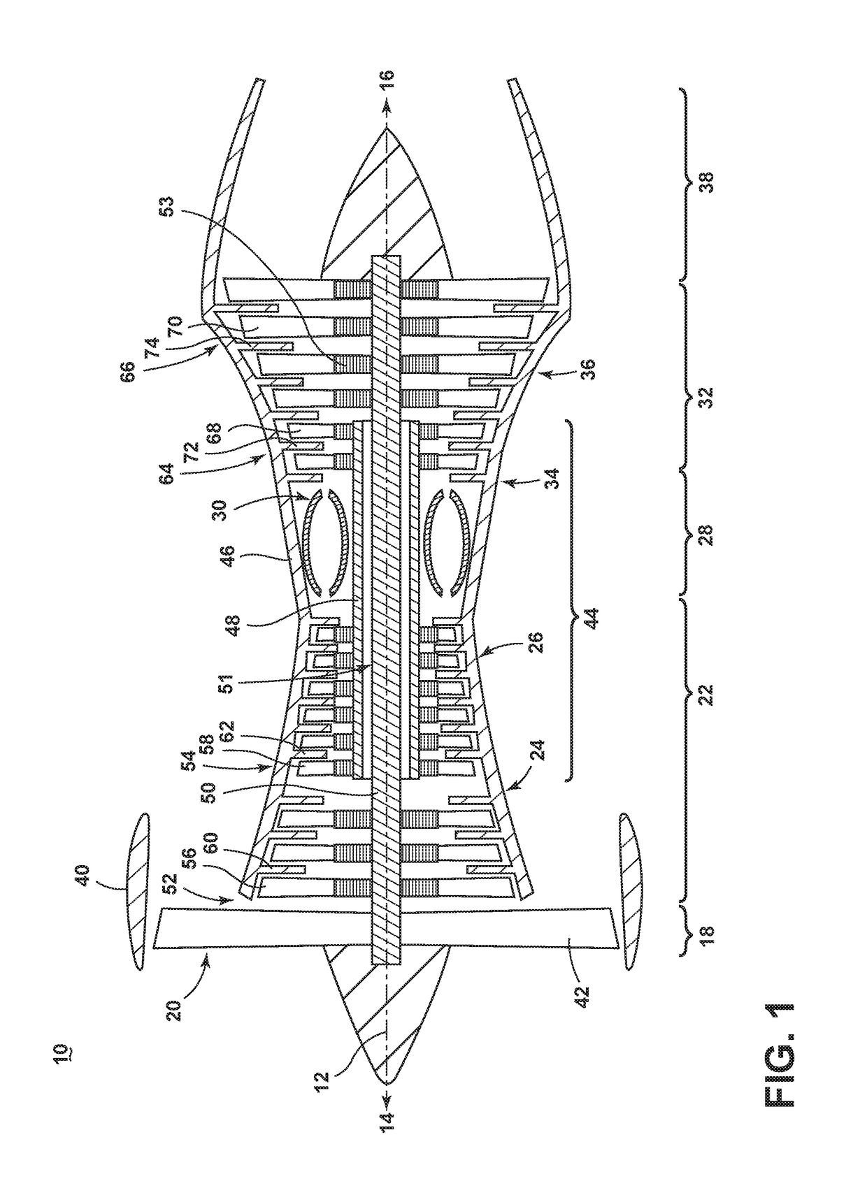
[0012]As used herein, the terms “axial” or “axially” refer to a dimension along a longitudinal axis of an engine. The term “forward” or “upstream” used in conjunction with “axial” or “axially” refers to moving in a direction toward the engine inlet, or a component being relatively closer to the engine inlet as compared to another component. The term “aft” or “downstream” used in conjunction with “axial” or “axially” refers to...


PUM


Abstract

A stator rim structure for a gas turbine engine comprises a stator having an end wall and a discourager defining a channel therebetween. The end wall is adjacent to a hot gas flow and the discourager is adjacent to a purge flow. A rotor has an angel wing extending into the channel. At least one supply passage is disposed within the stator and extends through the discourager and at least one aperture fluidly couples the supply passage with the channel. A flow of cooling air is fed from the supply passage into the aperture and into the channel to form a fluidic dam discouraging ingestion of the hot gas flow.

Description

BACKGROUND OF THE INVENTION[0001]Turbine engines, and particularly gas or combustion turbine engines, are rotary engines that extract energy from a flow of combusted gases passing through the engine onto a multitude of rotating turbine blades. Gas turbine engines have been used for land and nautical locomotion and power generation, but are most commonly used for aeronautical applications such as for aircraft, including helicopters. In aircraft, gas turbine engines are used for propulsion of the aircraft. In terrestrial applications, turbine engines are often used for power generation.[0002]Gas turbine engines for aircraft comprise multiple compressor stages designed with a plurality of bands of blades rotated by a rotor and bands of static vanes disposed between the blades. The compressor stages compress the air that is then moved to a combustor and a turbine. The compressor vanes are disposed with seals, limiting airflow leakage to upstream areas of the compressor, which can reduce...

Claims


Application Information

Patent Timeline
IPC IPC(8): F01D5/08F01D25/12F01D9/04
CPCF01D5/081F01D9/041F05D2240/128F05D2220/32F01D25/12F01D5/02F01D11/04F01D5/082F01D11/001Y02T50/60
Inventor RATZLAFF, JONATHAN RUSSELLMONTGOMERY, JULIUS JOHNHOGAN, MICHAEL THOMAS
Owner GENERAL ELECTRIC CO
Why Eureka
Try Eureka