Hybrid vehicle control apparatus and method

a hybrid vehicle and control apparatus technology, applied in vehicle position/course/altitude control, process and machine control, instruments, etc., can solve the problems of “drivability” problems, deterioration of vehicle performance as perceived by the driver, and downsized engines produce correspondingly lower levels of low speed torque compared with conventionally-sized engines. , to achieve the effect of reducing the overall fuel consumption, safe operation, and reducing the demands on the vacuum pump in the housing

Inactive Publication Date: 2010-07-22
FORD GLOBAL TECH LLC
View PDF6 Cites 5 Cited by
  • Summary
  • Abstract
  • Description
  • Claims
  • Application Information

AI Technical Summary

Benefits of technology

[0022]A pressure of typically between 1 mbar and 3 mbar is maintained in the flywheel housing by a vacuum pump that is usually electrically driven. This housing vacuum pump is periodically operated to maintain the necessary pressure levels and at a frequency that depends upon the performance of the sealing system. The electrical power required to operate this pump reduces the overall fuel consumption improvement of the flywheel energy storage and recovery system and the pump itself has to be capable of working on a pressure gradient from atmospheric pressure (of typically 1 ba

Problems solved by technology

However, particularly in the case where the prime mover is an internal combustion engine, a downsized engine produces correspondingly lower levels of low speed torque compared with a conventionally-sized engine.
This is likely to cause “drivability” problems.
For example, when pulling away from rest and when the flywheel has low or zero levels of stor

Method used


Image

  • Hybrid vehicle control apparatus and method
  • Hybrid vehicle control apparatus and method

Examples


Embodiment Construction

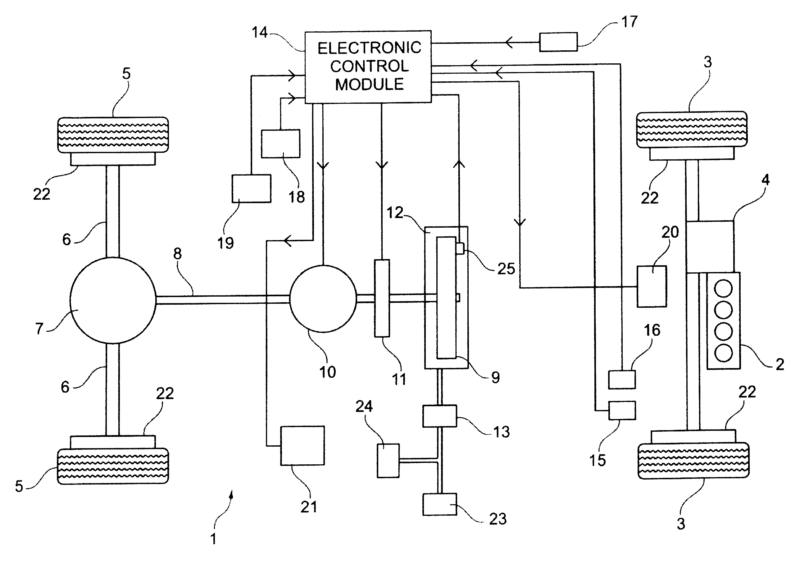
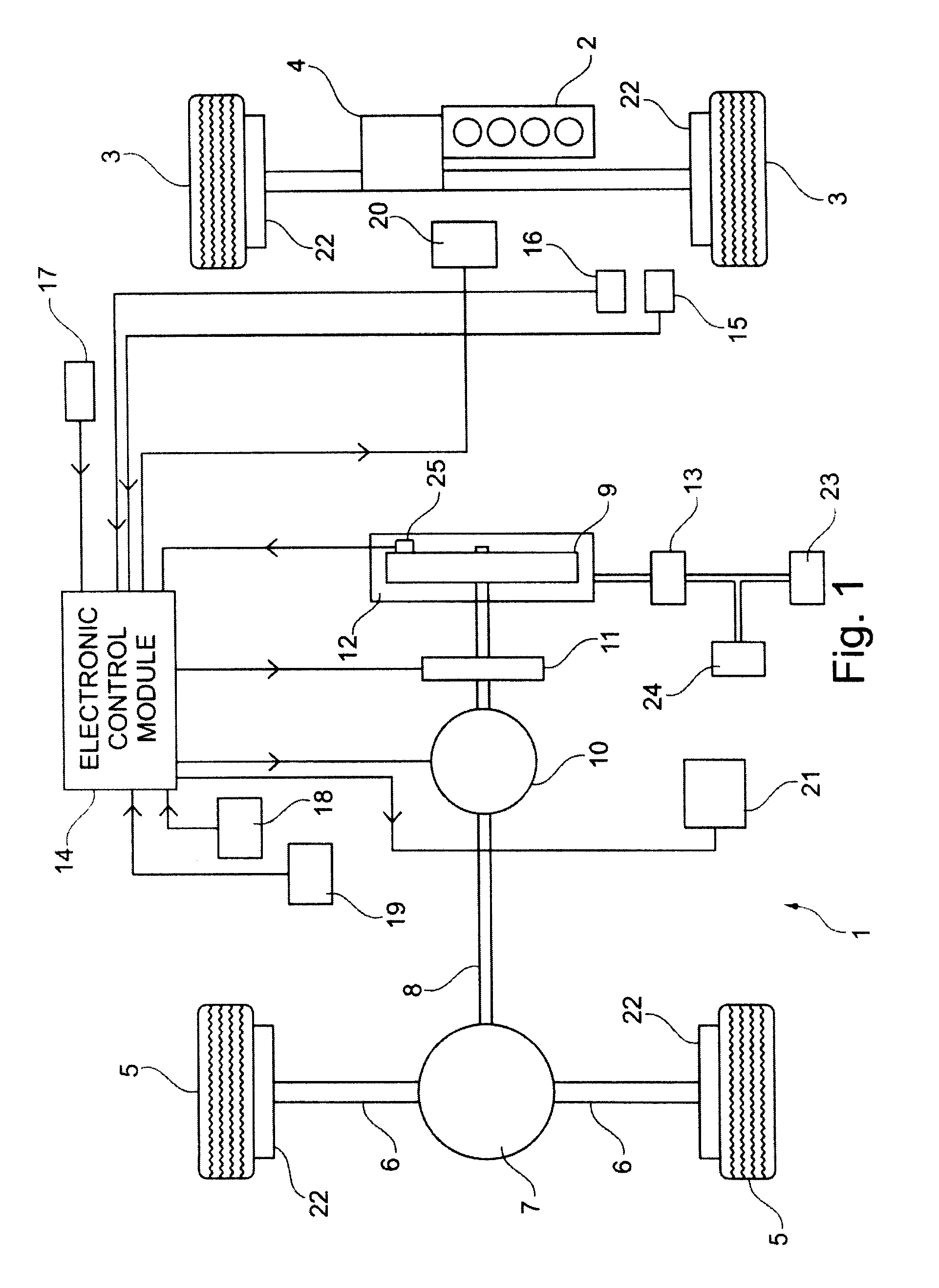
[0025]With reference to the drawing, a vehicle 1 is equipped with an internal combustion engine 2 which provides motive power solely to a first set of wheels 3 through a gearbox and final drive assembly 4.

[0026]A second set of wheels 5 is connected via half shafts 6 and a final drive and differential unit 7 to a propshaft 8. The propshaft can drive and be driven by a flywheel 9. Interposed between the propshaft 8 and flywheel 9 is a transmission unit 10 having a continuously variable gear ratio. An electro hydraulic clutch 11 is provided for decoupling the CVT 10 (and consequently the wheels 5) to and from the flywheel 9 under certain operating conditions.

[0027]A pressurised supply of oil is supplied to the CVT 10 by an oil pump (not shown) which is driven by the propshaft 8.

[0028]The flywheel is contained within an evacuated housing 12 to which is connected a housing vacuum pump 13.

[0029]An electronic control module ECM 14 receives inputs from an accelerator pedal position sensor 1...


PUM


Abstract

A hybrid vehicle has an internal combustion engine 2 and a flywheel 9. Storage and release of energy by the flywheel 9 is enabled by a continuously variable transmission 10 and clutch 11 under the control of an electronic module 14. The amount of energy transferred from the vehicle one to the flywheel 9 during a deceleration manoeuvre is maximised by increasing the engine speed. As a result, the engine does more work against the braking force of the accelerating flywheel and causes the flywheel to spin up to a higher rotational speed.

Description

BACKGROUND OF THE INVENTION[0001]This invention relates to an apparatus and method for controlling a vehicle having a prime mover and a secondary mover which incorporates an energy storage device. The invention has particular application to a hybrid vehicle whose prime mover is an internal combustion engine and whose secondary mover incorporates a flywheel but is not limited to this combination.[0002]SAE technical paper 2008-01-0083, Apr. 14-17, 2008, describes an arrangement consisting of a continuously variable transmission (CVT) connected between the engine and gearbox of a vehicle and configured to drive a flywheel through a gearset. The arrangement can add or subtract power to that supplied by the engine to a driven pair of wheels of the vehicle. The flywheel can be spun up in order to capture the kinetic energy of the vehicle as it decelerates. This is regenerative braking.[0003]US 2008 / 0105475 discloses an automotive vehicle having a powertrain for the vehicle, a flywheel and...

Claims


Application Information

Patent Timeline
IPC IPC(8): G06F19/00
CPCB60K6/105B60W20/10B60K6/52B60K6/543B60W10/06B60W20/00Y02T10/6204Y02T10/6221Y02T10/6265Y02T10/6282Y02T10/7033Y02T10/92B60W10/02B60W2510/02B60K6/48Y02T10/62B60K6/30Y02T10/70
Inventor BOWMAN, TIM JAMESHELLE-LORENTZEN, ROBERTJOSEPHINE KEES, DON ANDREAS
Owner FORD GLOBAL TECH LLC
Why Eureka
Try Eureka