
Ear canal obstruction detecting acoustical stimulation ear probe

a technology of acoustical stimulation and ear canal, which is applied in the field of ear canal status and ear canal obstruction detecting acoustical stimulation ear probe, can solve the problems of not having electro acoustical components to stimulate the ear or record sound from the ear canal, and the device does not contain any electro acoustical components to stimulate the ear, so as to achieve better and precise ear-probe placement and fitting, and reduce the ‘ refer

Active Publication Date: 2010-07-29
PATH MEDICAL
View PDF13 Cites 42 Cited by
  • Summary
  • Abstract
  • Description
  • Claims
  • Application Information

AI Technical Summary

Benefits of technology

[0024]The invention thus provides a probe with integrated lamp or variable frequency emitter, which allows better probe placement without the need of any additional light.
[0029]In order to detect occlusions of the ear-canals a light source or frequency emitter is integrated into the probe illuminating the outer ear-canal during insertion of the ear-probe. The tester will therefore be able to detect an occlusion and take the necessary steps for cleaning or postponing the acoustic testing. Furthermore the tester will be able to detect other problems with the ear canal (such as anatomical structural problems where the ear-canal is strongly bowed). This allows the tester a better and exact ear-probe placement and fitting. Again, the better the ear-probe is fitted the lower the ‘REFER’ rate will be.

Problems solved by technology

The poor visibility makes it hard to achieve good probe placement with the criteria named above.
Some examiners already make use of torches (flashlights) to overcome the issue, but these tie up a hand often needed for probe positioning.
These devices, however, do not contain any electro acoustical components to stimulate the ear or to record sound from the ear canal.

Method used


Image

  • Ear canal obstruction detecting acoustical stimulation ear probe
  • Ear canal obstruction detecting acoustical stimulation ear probe
  • Ear canal obstruction detecting acoustical stimulation ear probe

Examples


Embodiment Construction

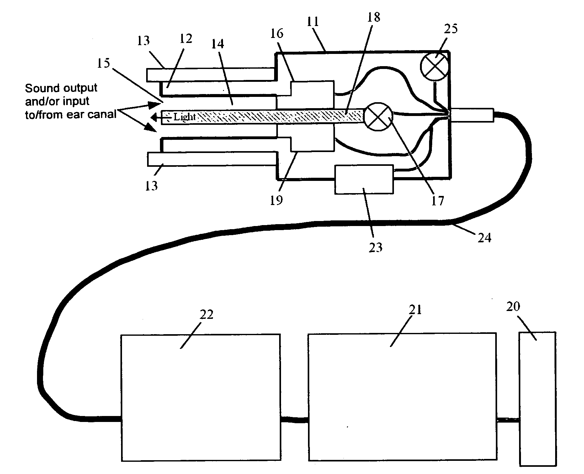
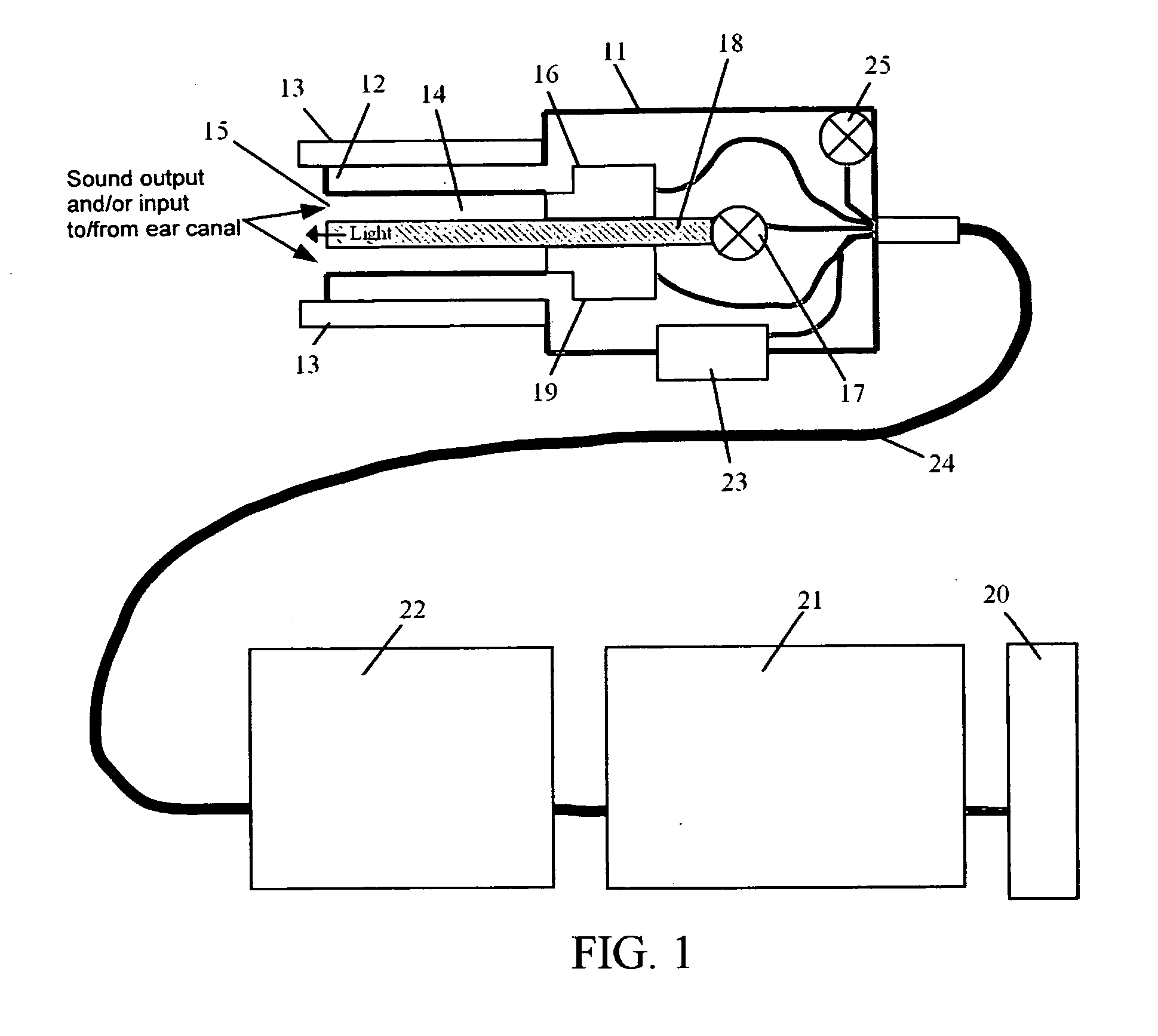
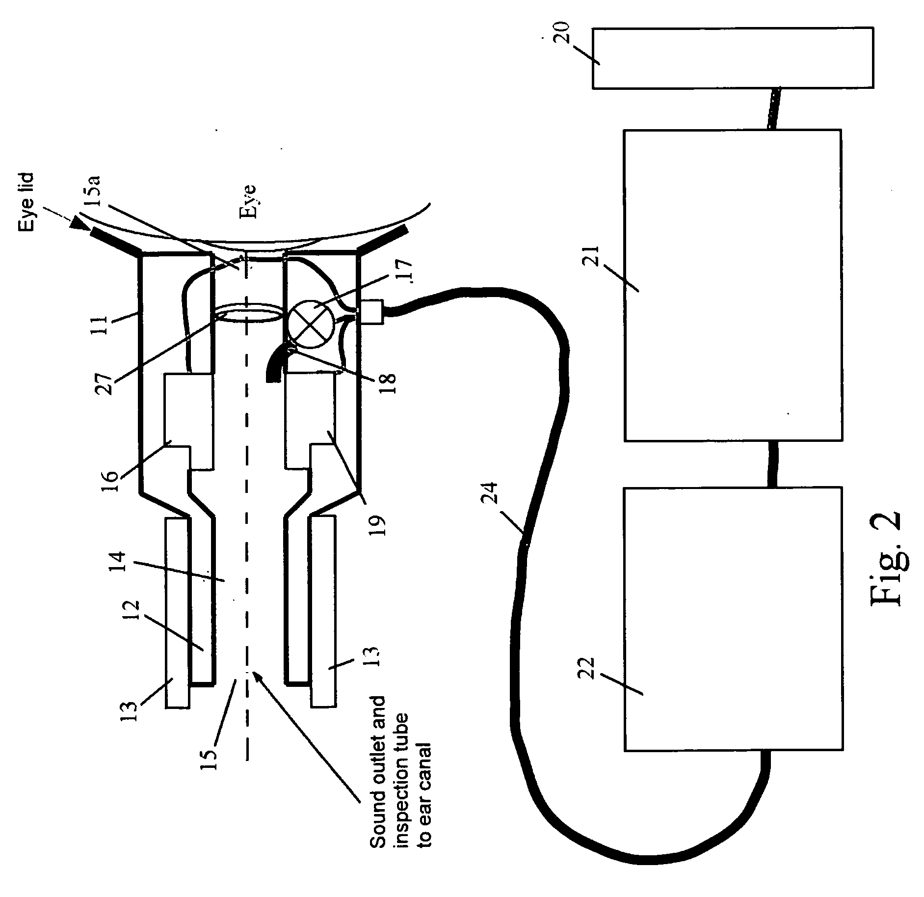
[0036]FIG. 1 is a cross-sectional view of one preferred embodiment of the illuminated ear probe 10. It consists of a flexible soft housing 11 with an exterior sized for grasping and positioning of the probe 10. The housing 11 has a tip 12 constructed of a material, which will form a seal with the inner ear canal. In this embodiment, a plurality of interchangeable different sized ear tips 13 are removably mounted onto the tip 12 as required to seal different sized ear canals before testing.

[0037]The housing 11 defines an interior passageway 14 leading to an opening 15 defined by the tip 12 to view the interior of the ear canal when the probe 10 is placed.

[0038]Mounted within the housing 11 is a speaker 16 and a lamp 17 attached to an optical duct 18. Mounted opposite the speaker 16 is a microphone 19, which picks up otoacoustical signals received in response to signals generated by the speaker 16. Preferred housing 11 materials are soft plastics, rubbers, and similar materials.

[0039]...


PUM


Abstract

An illuminated acoustical stimulation ear probe with outer ear illumination and a probe-fit status indicator.

Description

BACKGROUND OF THE INVENTION[0001]1. Field[0002]This invention relates to acoustical stimulation ear probes. In particular, it relates to an ear canal status and ear canal obstruction detecting acoustical stimulation ear probe with outer ear illumination and a probe-fit status indicator.[0003]2. State of the Art[0004]For several audiological methods, a defined sound stimulation of the ear is desired. Moreover, to record otoacoustic emissions, a microphone is to be coupled to the ear canal. The standard way to achieve this is a so-called ear probe, containing at least one speaker and one microphone coupled to the ear via so-called ear tips.[0005]To guarantee a defined stimulation over the complete desired frequency range, and to be able to record otoacoustic emissions, good probe placement is needed. Good in this context means that there should be a good seal between probe and ear canal, no earwax or other debris occludes the ear canal or the probe, and that the probe sits comfortably...

Claims


Application Information

Patent Timeline
Patent Type & Authority Applications(United States)
IPC IPC(8): A61B5/00
CPCA61B5/6885A61B1/227
Inventor ZOTH, PETERLODWIG, ANDREOSWALD, HANSJANSSEN, THOMAS
Owner PATH MEDICAL
Learn More