
Method and apparatus for blood withdrawal and infusion using a pressure controller

a pressure controller and controller technology, applied in the field of pressure controllers, can solve the problems of applicants' approach to vein collapse, too rapid vein collapse, and inability so as to reduce the pressure in the infusion line, reduce the pump speed, and reduce the infusion rate

Inactive Publication Date: 2009-06-11
GAMBRO LUNDIA AB
View PDF52 Cites 28 Cited by
  • Summary
  • Abstract
  • Description
  • Claims
  • Application Information

AI Technical Summary

Benefits of technology

The patent describes a blood withdrawal system that uses a controller to regulate the flow rate of blood through an extracorporeal circuit. The controller compensates for temporary vein collapse and adjusts the pump speed to compensate for changes in pressure. The system also includes a blood flow rate limit to prevent blood pressure from rising too high. The controller ensures that the blood pressure remains within safe limits and avoids hazardous situations. The system optimizes blood flow and ensures that blood withdrawal and infusion pressures are controlled in real-time. Overall, the system provides a safe and efficient means to withdraw blood from patients during treatment.

Problems solved by technology

For example, vein collapse can temporarily occur when the patient moves or a venous spasm causes the vein to collapse in a manner that is too rapid to anticipate and temporary.
Applicants' approach to vein collapse is counterintuitive and contrary to the approach disclosed in the '237 and '529 patents.
Peripheral vein access presents unique problems that make it difficult for a blood withdrawal controller to maintain constant flow and not to create hazards for the patient.
These problems are unlike those encountered with conventional dialysis treatments that rely on a surgically created arterio-venous shunt or fistula to withdraw blood and are administered in controlled dialysis centers.
Using the present controller, for example, a patient may stand up during treatment and thereby increase the static pressure head height on the infusion side resulting in a false occlusion.

Method used


Image

  • Method and apparatus for blood withdrawal and infusion using a pressure controller
  • Method and apparatus for blood withdrawal and infusion using a pressure controller
  • Method and apparatus for blood withdrawal and infusion using a pressure controller

Examples


Embodiment Construction

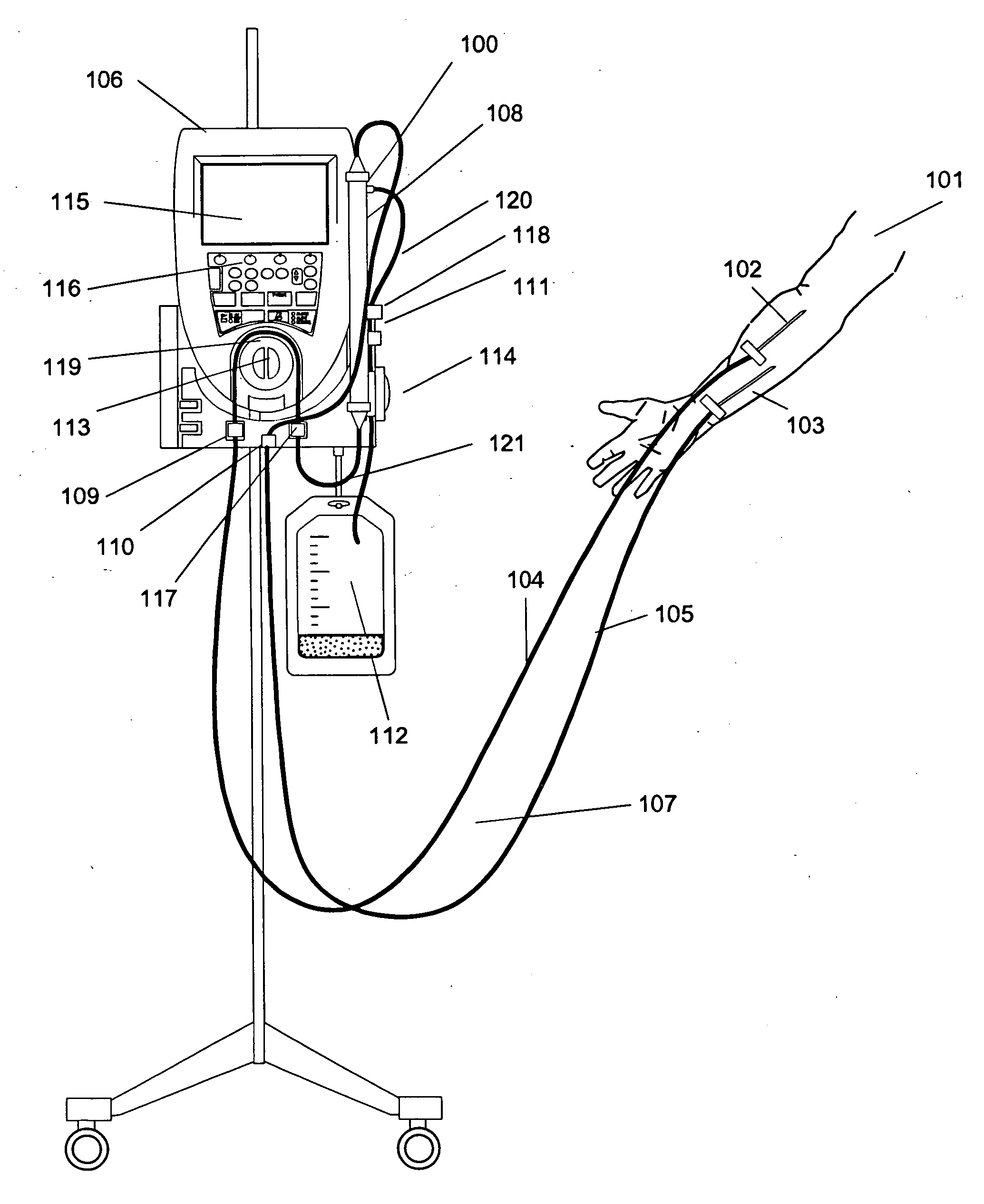
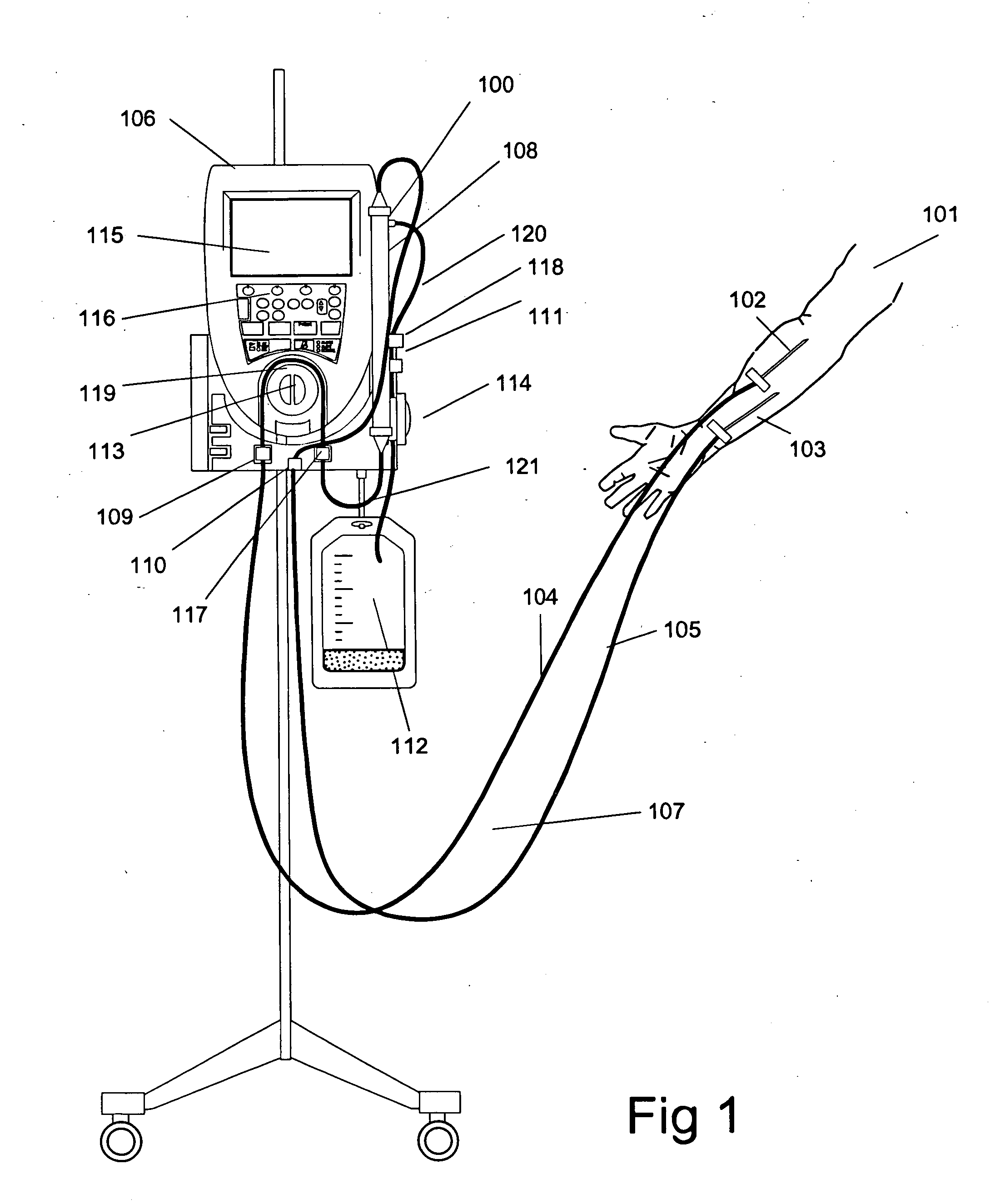
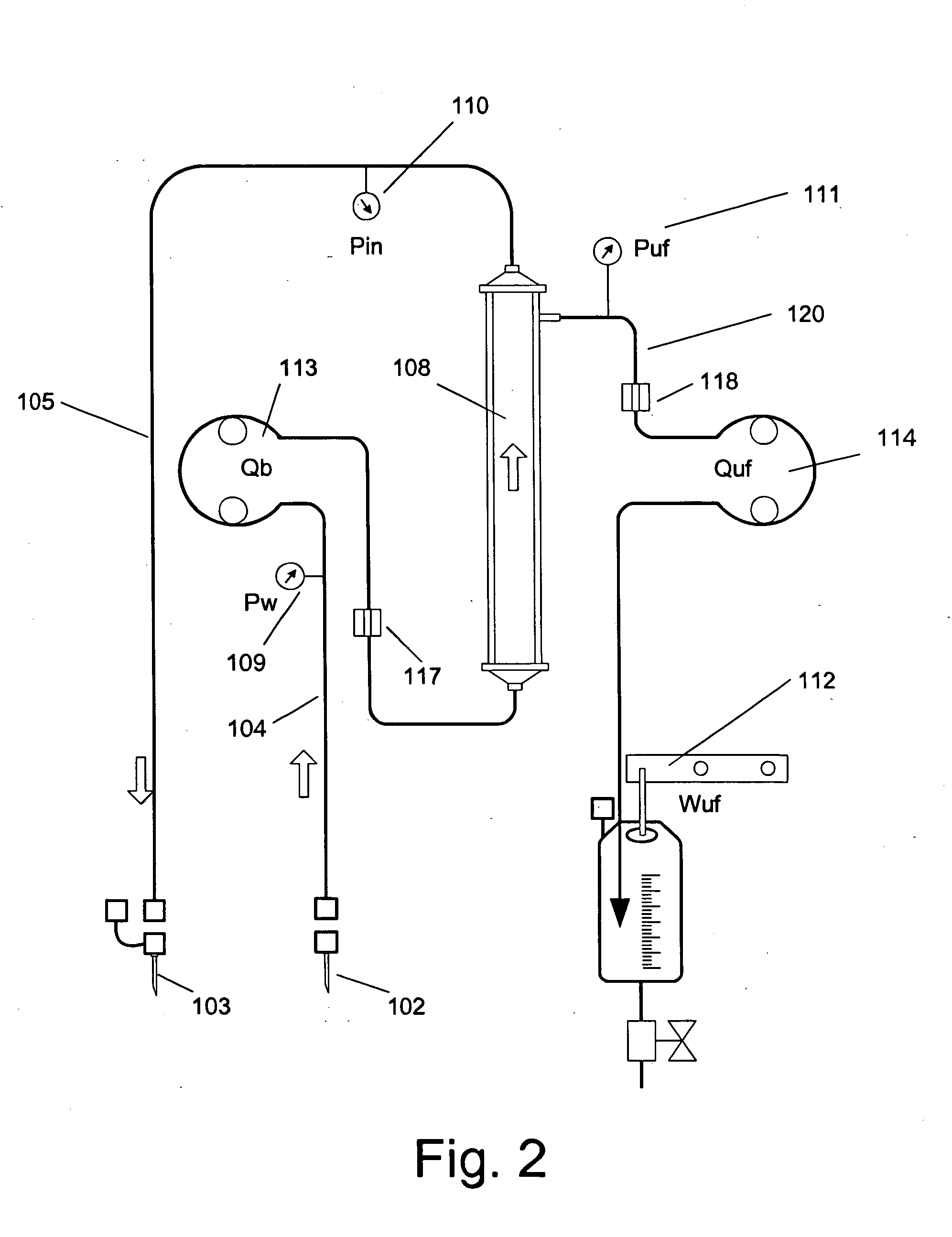
[0036]A pump controller has been developed which may be incorporated in an extracorporeal blood circuit system. This system in an exemplary embodiment withdraws blood from a peripheral vein of a patient, processes the blood, e.g., passes the blood through a pump and filter, and returns the blood to the same or another peripheral vein. The pump controller monitors the blood pressure in the blood circuit and adjusts the speed of the pump (and hence the blood flow rate through the circuit) to comply with multiple limits on the pressure level and flow rates in the circuit. In addition, the controller promptly reacts to any changes in the pressure in the circuit.

[0037]The withdrawal and infusion of blood from a peripheral vein (or peripheral artery) in a mammalian patient (whether the patient is a human or other mammal) presents unique problems, which have been successfully addressed by the controller disclosed here. A peripheral vein in a human is a hollow tube, having approximately a 2...


PUM


Abstract

A method and apparatus for controlling blood withdrawal and infusion flow rate with the use of a pressure controller. The pressure controller uses pressure targets based upon occlusion limits that are calculated as a function of flow. The controller has the ability to switch from controlling withdrawal pressure to controlling infusion pressure based upon the detection of an occlusion. The controller distinguishes between partial and total occlusions of the withdrawal vein providing blood access. Depending on the nature of occlusion, the controller limits or temporarily reverses blood flow and, thus, prevents withdrawal vessel collapse or reverses blood flow to quickly infuse blood into the vessel without participation from operator.

Description

RELATED APPLICATIONS[0001]This is a divisional application of U.S. patent application Ser. No. 11 / 154,569 (U.S. Pat. No. 7,462,161) filed Jun. 17, 2005 which is a continuation application of application Ser. No. 10 / 601,574 filed Jun. 24, 2003 which is a divisional application of U.S. patent application Ser. No. 09 / 703,702 (now U.S. Pat. No. 6,585,675) filed on Nov. 2, 2000, the entirety of all applications are incorporated by reference herein.FIELD OF INVENTION[0002]The invention relates to the field of pressure controllers for fluidic pumping systems and, in particular, to pressure controllers for intravenous blood pumps.BACKGROUND OF THE INVENTION[0003]There are a number of medical treatments, such as ultrafiltration, apheresis and dialysis, that require blood to be temporarily withdrawn from a patient and returned to the body shortly thereafter. While the blood is temporarily outside of the body, it flows through an “extracorporeal blood circuit” of tubes, filters, pumps and / or o...

Claims


Application Information

Patent Timeline
Patent Type & Authority Applications(United States)
IPC IPC(8): A61M1/36A61M1/16A61M1/34B01D61/00B01D61/22
CPCA61M1/1692A61M1/34A61M1/3656B01D61/22A61M1/3639A61M2205/15A61M2205/3331A61M2205/3334A61M2205/50A61M2205/502A61M1/341A61M2205/18
Inventor O'MAHONY, JOHN J.GELFAND, MARKRYCHLICK, EDWARD G.
Owner GAMBRO LUNDIA AB
Learn More