Push-Cable for Pipe Inspection System

a technology for inspection systems and push-cables, which is applied in the direction of power cables, cables, insulated conductors, etc., can solve the problems of single mode failure in the central push-rod, and the push-cable with a semi-rigid central push-rod also has the drawback of a single mode failur

Active Publication Date: 2010-08-19
SEEKTECH
View PDF14 Cites 47 Cited by
  • Summary
  • Abstract
  • Description
  • Claims
  • Application Information

AI Technical Summary

Problems solved by technology

A conventional push-cable with a semi-rigid central push-rod also has the drawback of a single mode of failure in the central push-rod if it is over-stressed by too narrow a bend, for example.

Method used


Image

  • Push-Cable for Pipe Inspection System
  • Push-Cable for Pipe Inspection System
  • Push-Cable for Pipe Inspection System

Examples


Embodiment Construction

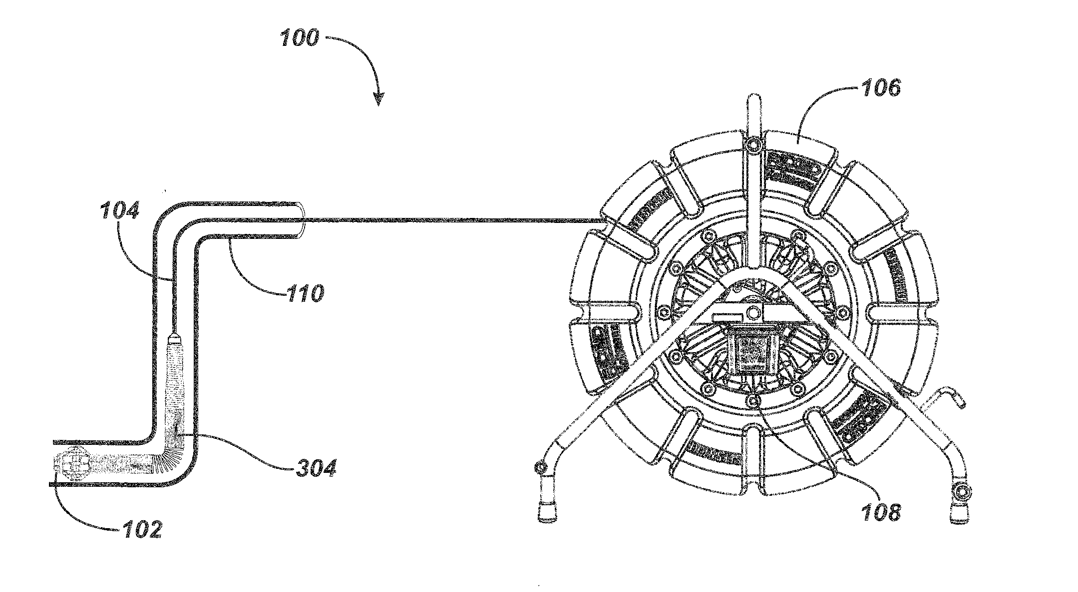
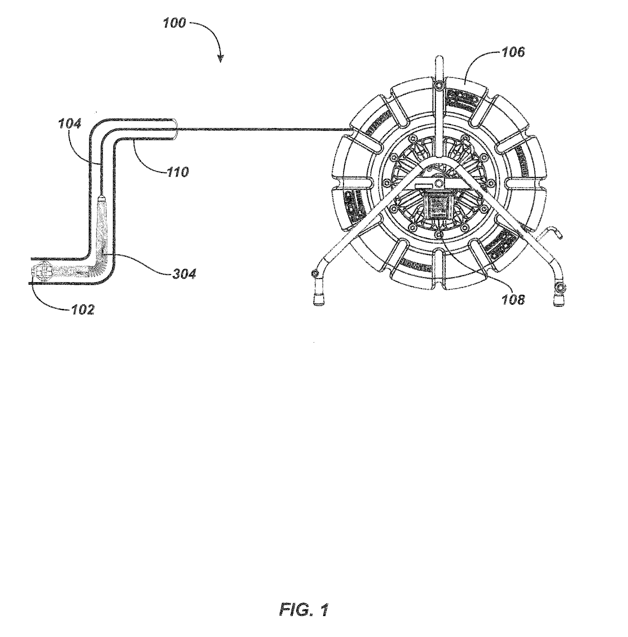
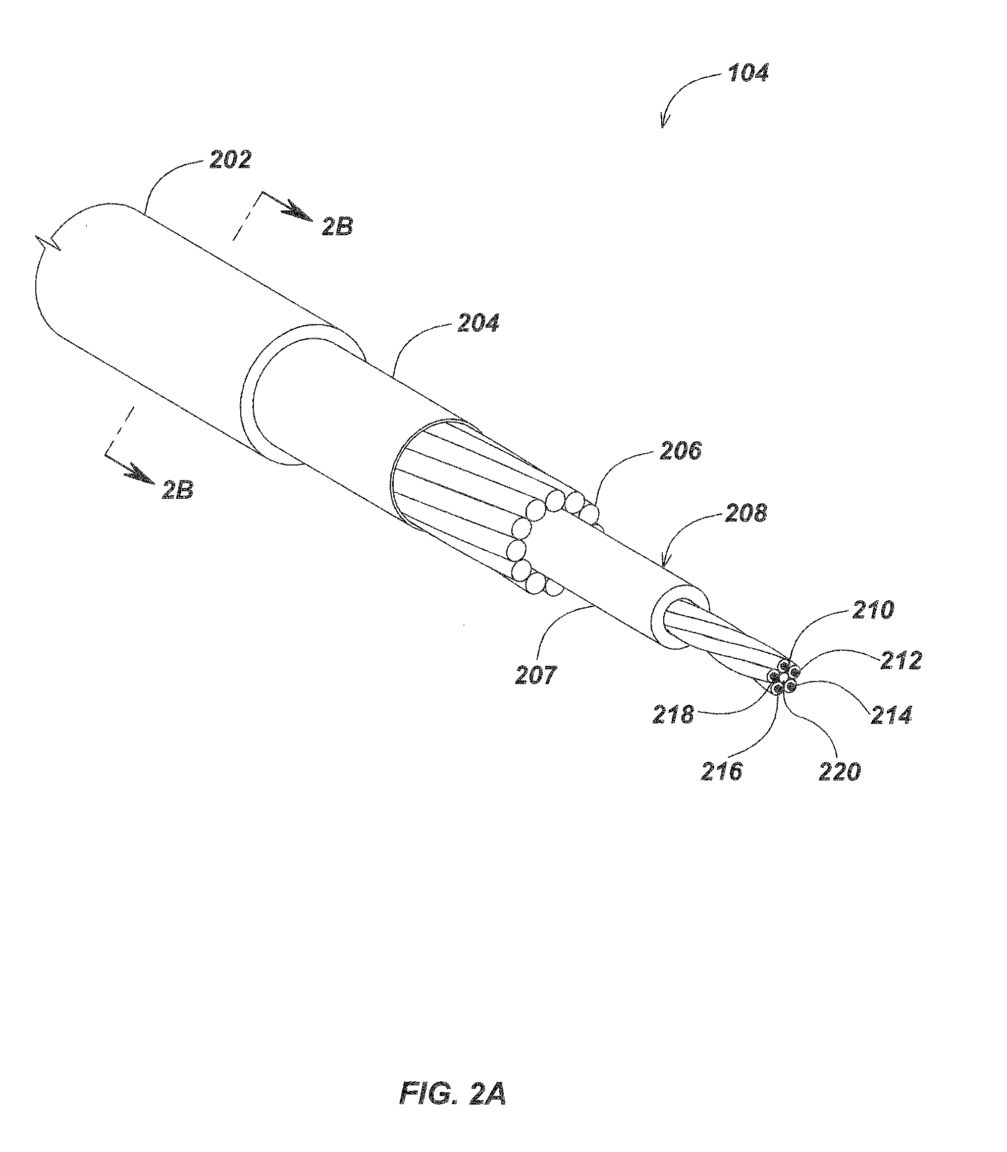
[0027]The present invention also provides an innovative high-performance push-cable with the advantage, compared to existing designs, of a smaller diameter and a more flexible construction with a significantly reduced bend radius, more suitable to miniaturized inspection cameras and adaptable to more varied environments including smaller pipes and other voids, conduits or spaces requiring more flexibility to access.

[0028]The present invention also provides an inspection push-cable that does not require electrical termination at the rear of the protective spring surrounding the camera head but allows the inner conductors to plug directly into the camera head through spring-loaded pins contacting conductive pads within the camera head. This innovation results in improved ease of construction and improved bend-radius during inspections.

[0029]The present invention provides a novel camera head for use in pipe inspection systems with innovations in design which improve heat dissipation, s...


PUM

PropertyMeasurementUnit
internal diameteraaaaaaaaaa
diameteraaaaaaaaaa
diameteraaaaaaaaaa

Abstract

In accordance with the present invention a push-cable comprises a central core including a least one conductor, a plurality of non-metallic resilient flexible stiffness members surrounding the core, and a layer of sheathing surrounding the stiffness members.

Description

CROSS-REFERENCE TO RELATED APPLICATION AND PATENT[0001]This application is related by common authorship and field of application to U.S. Pat. No. 5,939,679 of Aug. 17, 1999, Olsson, entitled VIDEO PUSH-CABLE, and patent application Ser. No. 11,679,092 of 26 Feb. 2007, Olsson, entitled LIGHTWEIGHT SEWER CABLE, both of which are here incorporated by reference.BACKGROUND[0002]1. Field of the Invention[0003]The present invention relates generally to systems for inspecting the interior of pipes and other conduits or voids, and more specifically to the design of push-cables used to move an inspection camera into pipes, conduits or other hard-to-access areas.[0004]2. Description of the Related Art[0005]There are many situations where it is desirable to internally inspect long lengths of pipe that are already in place, either underground, in a building, or underwater. For example, sewer and drain pipes frequently must be internally inspected to diagnose any existing problems and to determin...

Claims


Application Information

Patent Timeline
Patent Type & Authority Applications(United States)
IPC IPC(8): H04N7/18H01B7/17
CPCH01B7/182H01B7/041H01B11/00
Inventor OLSSON, MARK S.CHAPMAN, ERIC M.
Owner SEEKTECH
Why Eureka
Try Eureka