Loading and Unloading Arrangement for a Vehicle

a technology for loading and unloading a vehicle and a support member, which is applied in the direction of loading transportation vehicles, transportation items, vehicles with parallel load movement, etc., can solve the problems of not being able to easily unload a tray located on the support member to ground level and leave this tray behind, and not being able to vertically drop a transport load from a support member

Inactive Publication Date: 2010-08-26
CLINE TECH
View PDF7 Cites 12 Cited by
  • Summary
  • Abstract
  • Description
  • Claims
  • Application Information

AI Technical Summary

Benefits of technology

[0038]In operation, the truck can be reversed to cause the wheels to rotate and thereby move the loading tray rearwardly. Rearward movement of the tray relative to the support member is controlled by the winch. As the loading tray moves rearwardly, the center of gravity of the tray can pass the axis of rotation of the at least one wheel. The loading tray can then tilt downward toward the ground. The control device can be used to control the speed of movement and the angle of tilt of the loading tray relative to the support member during this operation. One or more rollers fitted to the rearward edge of the support member can contact a portion of the loading tray during this action. Continued rearward movement can tilt the loading tray about the rollers. As the loading tray tilts, contact with the at least one wheel can be lost. Downward and rearward travel of the loading tray can continue, controlled by the winch control device, until the tray contacts the ground. When the rear of the loading tray rests on the ground, reversing of the truck is stopped, and gravity forces due to the weight of the tray against the rear of the truck can cause forward movement of the truck. The winch can be used to move the front edge of the loading tray around and off the one or more rollers, and lower the loading tray to the ground. Once lowered to the ground, the cable of the winch can be disconnected, and the loading tray can be left behind.
[0039]To load the loading tray on to the support member of the truck, the truck is reversed up to and in reasonable alignment with the loading tray. The winch cable is attached to the loading tray. The winch is used to lift the front of the loading tray, automatically aligning it, up and over the one or more rollers. The loading tray's side guards or guides can help align the loading tray with the support member of the truck. As the winch cable is drawn in further, the loading tray can roll up on the rollers, pulling the truck or trailer back toward it, to a point of balance, where continuing winching can pull the loading tray down toward a level plane, and forward toward a ‘transport’ position. Contact with the main wheels may occur during this operation, which may assist the loading tray, to roll forward. The truck may also roll forward a small amount during this operation. The angle of the loading tray is controlled during this operation by the positions of the rollers, the wheels, and the pull of the controller. Further winching / pulling of the controller cable can pull the loading tray fully onto the truck chassis. Adding air pressure to the suspension can lift the tray, body, loading tray, or load clear of the wheels, allowing normal truck operation.

Problems solved by technology

Each of these conventional loading and unloading arrangements has specific limitations.
Thus, loading and unloading arrangements adapted to tilt a support member to slide the transport load(s) off the support member of a vehicle are unable to easily unload a tray located on the support member to ground level and leave this tray behind.
Additionally, this arrangement cannot vertically drop a transport load from a support member.
This high angle can limit the types of load that can be used on this type of arrangement.
These lift units can take up a large amount of operational space on the support member of a vehicle, and can be heavy and expensive.
Accordingly, each existing loading and unloading arrangement is complicated, and expensive, having significant purchase, operating and maintenance cost.

Method used


Image

  • Loading and Unloading Arrangement for a Vehicle
  • Loading and Unloading Arrangement for a Vehicle
  • Loading and Unloading Arrangement for a Vehicle

Examples


Embodiment Construction

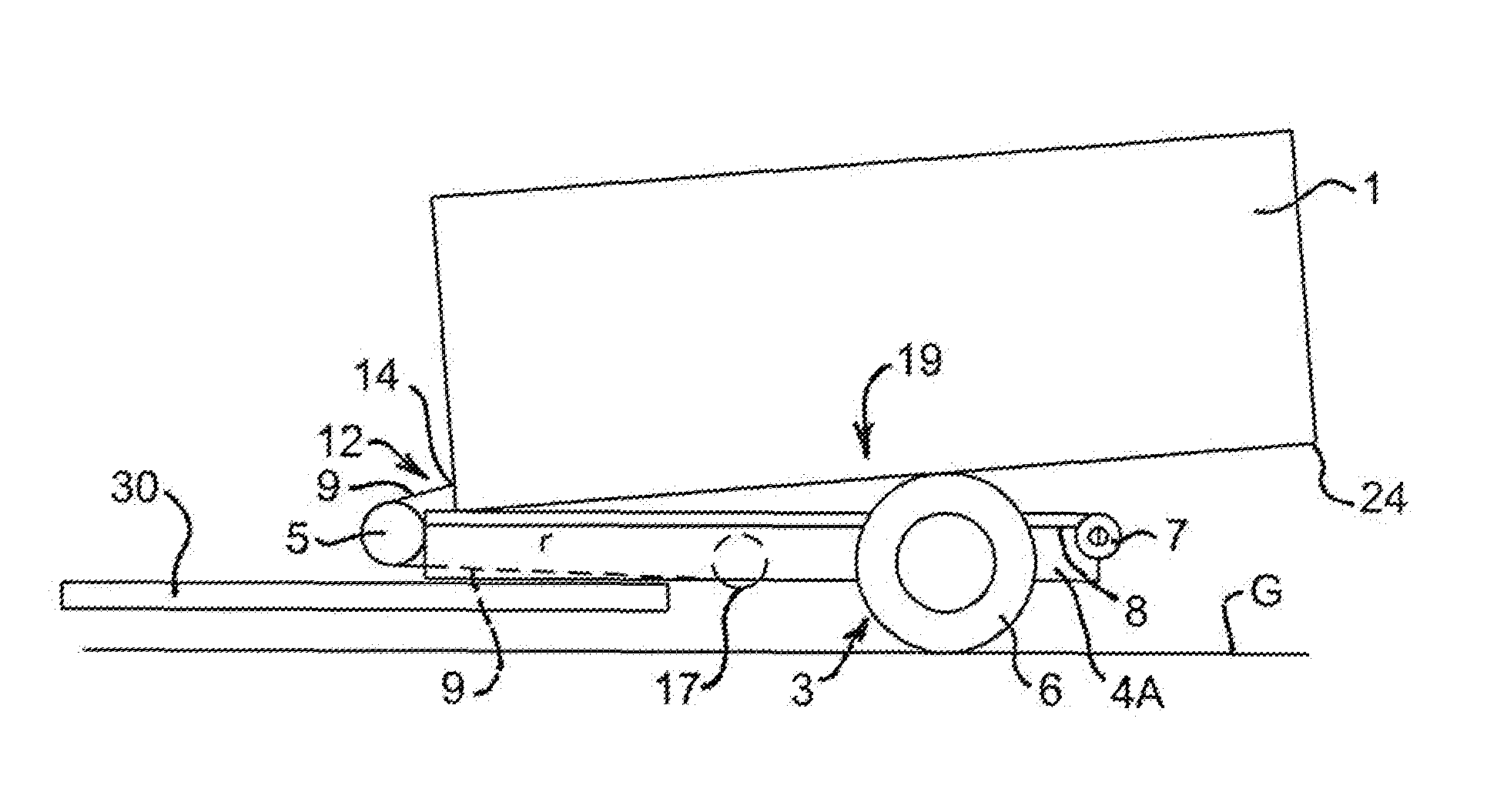
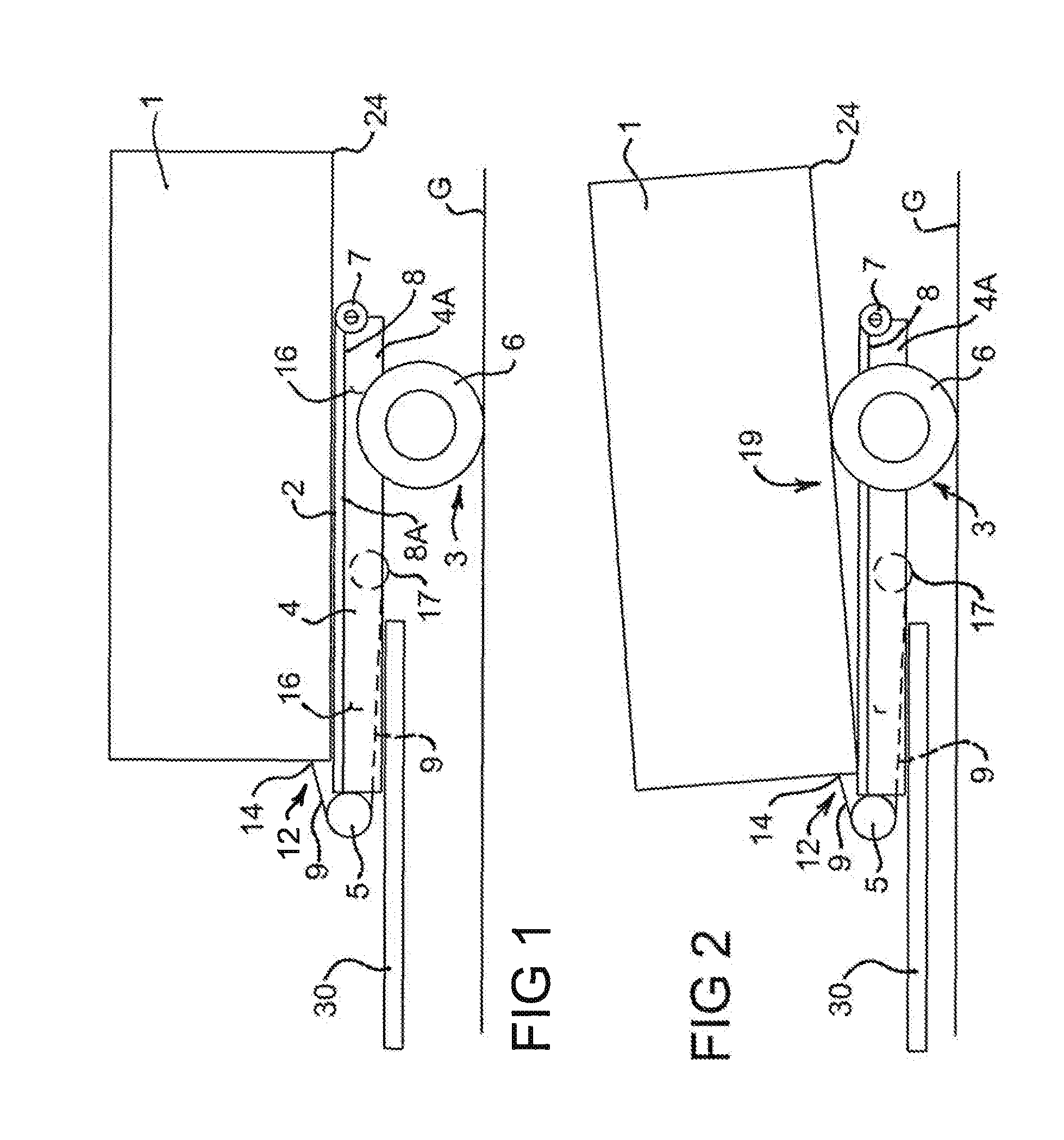
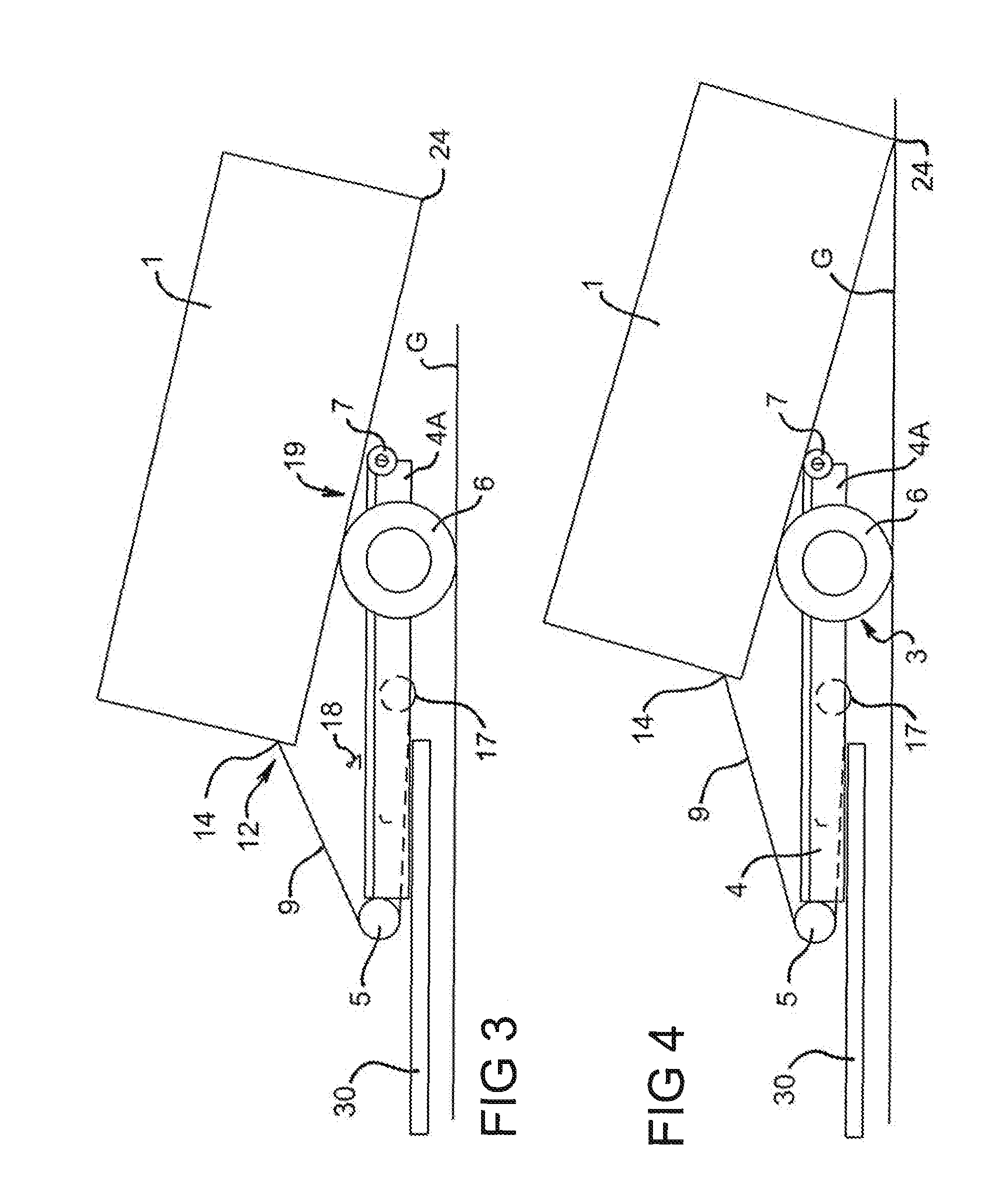
[0047]FIGS. 1 to 6 provide a sequential series of figures illustrating the steps in unloading and loading a vehicle, in this case a trailer 4, that includes one preferred embodiment of a loading and unloading arrangement according to the present invention. As can be appreciated, unloading a transport load, in this case in the form of a container 1, from the trailer 4 is illustrated by following the sequence of figures starting from FIG. 1 through to FIG. 6. Conversely, loading the container 1 onto the trailer 4 is illustrated by following the figures in reverse order starting from FIG. 6 through to FIG. 1.

[0048]While the transport load is shown in the form of a container 1 in the present figures, the transport load could be any suitable object such as a tray, container, box, platform or the like. Similarly, it should be understood that while the vehicle 4 is shown in the form of a trailer 4 in the present figures, the vehicle could be any suitable wheeled body such as for example a ...


PUM


Abstract

An arrangement for a vehicle, for loading and unloading a transport load on or from the vehicle, vehicle includes a support member having a surface onto which the transport load can be located and a ground engaging wheel assembly. At least one wheel of the wheel assembly is positioned proximate to the support member and the arrangement has at least one height adjustment device for operatively engaging the transport load with the at least one wheel. As the vehicle is moved with the transport load engaged with the wheel, the transport load is able to move across and / or along the support member, in the direction in which the vehicle is moved, by rotation of the wheel.

Description

FIELD OF THE INVENTION[0001]The present invention generally relates to a loading and unloading arrangement for a vehicle. The invention is particularly applicable to a loading and unloading arrangement for trucks and trailers having a tilt, slide, drop and retrieve action and it can be convenient to hereinafter disclose the invention in relation to that exemplary application. However, it is to be appreciated that the invention is not limited to that application and could be used in any vehicle having a support member onto which a transport load could be loaded and unloaded.BACKGROUND OF THE INVENTION[0002]The following discussion of the background to the invention is intended to facilitate an understanding of the invention. However, it should be appreciated that the discussion is not an acknowledgement or admission that any of the material referred to was published, known or part of the common general knowledge as at the priority date of the application.[0003]A large variety of load...

Claims


Application Information

Patent Timeline
Patent Type & Authority Applications(United States)
IPC IPC(8): B60P1/00B60P1/02B60P1/52
CPCB60P1/6427B60P1/52
Inventor CLINE, WILLIAM CHESTER
Owner CLINE TECH
Why Eureka
Try Eureka