Base plate system for shoulder arthroplasty and method of using the same

a base plate system and shoulder arthroplasty technology, applied in the field of shoulder arthroplasty, can solve the problems of deficiency of the rotator cuff which stabilizes a conventional arthroplasty, difficulty in reverse shoulder arthroplasty, and inability to adjust the locking mechanism without damaging the locking mechanism,

Inactive Publication Date: 2010-08-26
GROH GORDON I
View PDF57 Cites 167 Cited by
  • Summary
  • Abstract
  • Description
  • Claims
  • Application Information

AI Technical Summary

Problems solved by technology

In these patients, the rotator cuff which stabilizes a conventional arthroplasty is deficient.
Reverse shoulder arthroplasty continues to remain challenging.
There are separate issues both in implantation of devices and dealing with bone deficiency.
In this regard, current designs for base plates for shoulder arthroplasty do not allow for locking screws that can be redirected without damaging the locking mechanism.
Eccentric reaming remains the easiest mechanism to deal with bone loss, but this technique has its limits.
First, reaming can only typically correct defects of 10 degrees of version of the glenoid.
If the glenoid face is over narrowed via reaming, adequate seating and screw / peg fixation of an implant is very difficult if not impossible.
Unfortunately, this technique is extremely demanding and time consuming.
Further, the technique requires a graft which may not be available as a native bone, necessitating the use of an allograft.
Finally, graft to native bone healing is not assured and may lead to early or late failure of the prosthesis.

Method used


Image

  • Base plate system for shoulder arthroplasty and method of using the same
  • Base plate system for shoulder arthroplasty and method of using the same
  • Base plate system for shoulder arthroplasty and method of using the same

Examples


Embodiment Construction

[0020]Various embodiments of the present invention now will be described more fully hereinafter with reference to the accompanying drawings, in which some, but not all embodiments of the invention are shown. Indeed, various embodiments of the invention may be embodied in many different forms and should not be construed as limited to the embodiments set forth herein; rather, these embodiments are provided so that this disclosure will satisfy applicable legal requirements. Like numbers refer to like elements throughout. The singular forms “a,”“an,” and “the” include plural referents unless the context clearly dictates otherwise.

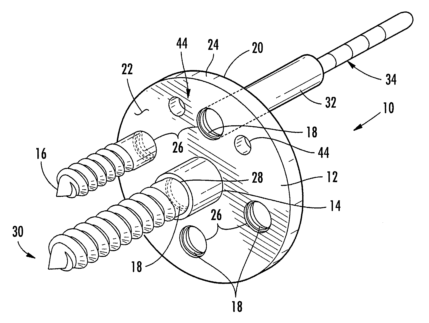
[0021]As shown generally in FIG. 1, embodiments of the present invention are directed to a base plate system 10 that generally includes a base plate 12, a central peg 14 extending from the base plate, a plurality of locking screws 16 configured to engage the bone, and a plurality of locking washers 18 configured to fix the locking screws with respect to the bas...


PUM


Abstract

Embodiments of the present invention provide systems and methods for use in a replacing a joint having a prepared bone surface. A base plate system according to one embodiment includes a base plate comprising a plurality of locking screw holes defined therethrough and first and second opposing surfaces, wherein the second surface is configured to be positioned adjacent to the prepared bone surface. The system also includes a central peg extending outwardly from the second surface of the base plate and configured to engage the prepared bone surface and a plurality of locking screws configured to be inserted within a respective locking screw hole and engage the prepared bone surface. In addition, the system includes a plurality of locking washers disposed within a respective locking screw hole and configured to receive a respective locking screw and lock the locking screw at a desired angle with respect to the base plate.

Description

CROSS-REFERENCE TO RELATED APPLICATIONS[0001]The present application claims priority from U.S. Provisional Application No. 61 / 154,429 filed Feb. 22, 2009, the contents of which are incorporated herein by reference.FIELD OF INVENTION[0002]Various embodiments of the present invention relate to shoulder arthroplasty and, in particular, to a base plate system for use in reverse arthroplasty and total arthroplasty procedures.BACKGROUND OF THE INVENTION[0003]Reverse shoulder arthroplasty is indicated for rotator cuff deficient arthritis of the shoulder. In these patients, the rotator cuff which stabilizes a conventional arthroplasty is deficient. By reversing the ball and socket configuration, a stable construct may be implanted which allows the intact deltoid muscle to contract under an improved lever arm. This reversal also allows for improved elevation of the shoulder.[0004]Reverse shoulder arthroplasty continues to remain challenging. There are separate issues both in implantation of ...

Claims


Application Information

Patent Timeline
Patent Type & Authority Applications(United States)
IPC IPC(8): A61F2/40A61B17/56
CPCA61B17/80A61B17/8033A61B17/8061A61B17/86A61F2/30749A61F2220/0025A61F2002/30514A61F2002/30736A61F2002/4085A61F2220/0008A61F2/4081
Inventor GROH, GORDON I.
Owner GROH GORDON I
Why Eureka
Try Eureka