Oven rack assemblies with release mechanisms and catches

a technology of oven rack and release mechanism, which is applied in the field of oven products, can solve the problems of affecting the operation of oven racks, and the subframe may tend to tip away from a horizontal plane, and achieve the effect of facilitating the sliding movement of oven racks and sliding systems

Active Publication Date: 2010-09-02
SSW ADVANCED TECH LLC
View PDF8 Cites 33 Cited by
  • Summary
  • Abstract
  • Description
  • Claims
  • Application Information

AI Technical Summary

Benefits of technology

[0014]In accordance with one aspect of the invention, an oven rack assembly is adapted for use within an oven cavity having oven cavity liner sides. The oven rack assembly includes an oven rack with means for supporting items to be cooked or otherwise heated within the oven cavity. The oven rack is manually extendable between a retracted position within the oven cavity, and an extended position where the oven rack is moved forwardly relative to the oven cavity. A slide system is provided which is coupled to the oven rack, and provides the capability of the oven rack to move between the retracted position and the extended position. A subframe is provided, with the subframe coupled to the slide system and normally positioned in a first location within the oven cavity. Retention / release means are manually operable by a user for retaining the subframe in the first location. In accordance with one aspect of the invention, the retention / release means are mounted to the slide system and comprise interaction means for maintaining retention of the subframe in the first location, through interaction with the oven liner sides.
[0018]In accordance with other aspects of the invention, an oven rack assembly in accordance therewith can be adapted for use with an oven cavity having oven liner sides and / or an oven liner rear surface. The assembly can include an oven rack extendable between retracted and extended positions, and a slide system coupled to the oven rack for moving the rack between these positions. A subframe can form a part of the oven rack assembly and support the oven rack and the slide system. The subframe can include a pair of catch portions formed at or near the rear of the subframe. The oven rack assembly can also include catch support means mounted within the oven cavity. The catch support means can include a series of catches for releasably capturing the catch portions on the subframe. In this manner, the subframe is substantially prevented from tipping forwardly as a result of the weight of the subframe and / or cantilever forces exerted on the subframe by the oven rack and the slide system. Still further, the catch support means operate so as to hold the subframe in place, thereby facilitating sliding movement of the oven rack and slide system.

Problems solved by technology

One difficulty which has existed for a number of years in the industry relates to manipulation of oven racks.
Still further, when manipulating the subframe, one difficulty which can arise is that the subframe may tend to tip away from a horizontal plane.

Method used


Image

  • Oven rack assemblies with release mechanisms and catches
  • Oven rack assemblies with release mechanisms and catches
  • Oven rack assemblies with release mechanisms and catches

Examples


second embodiment

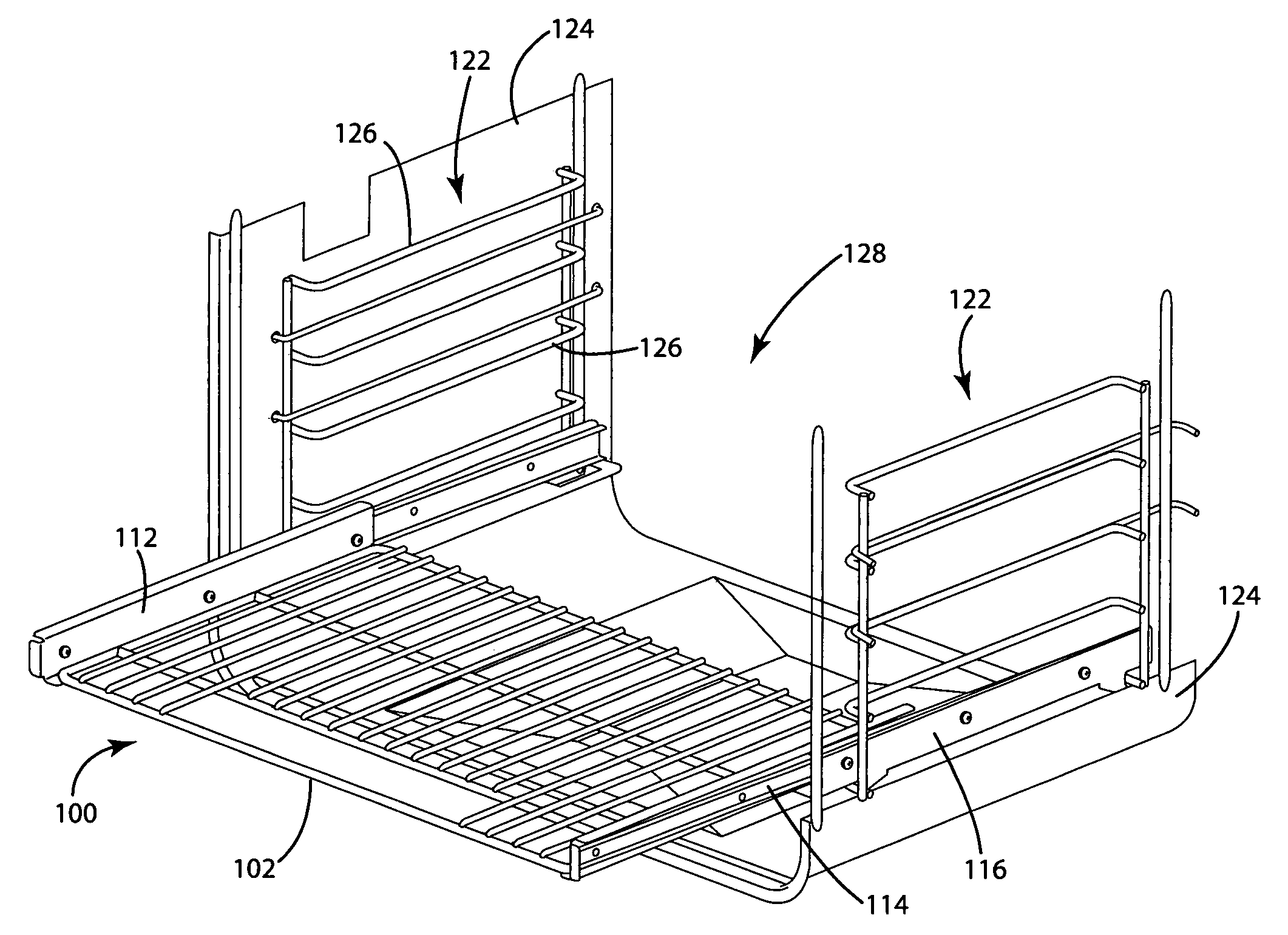
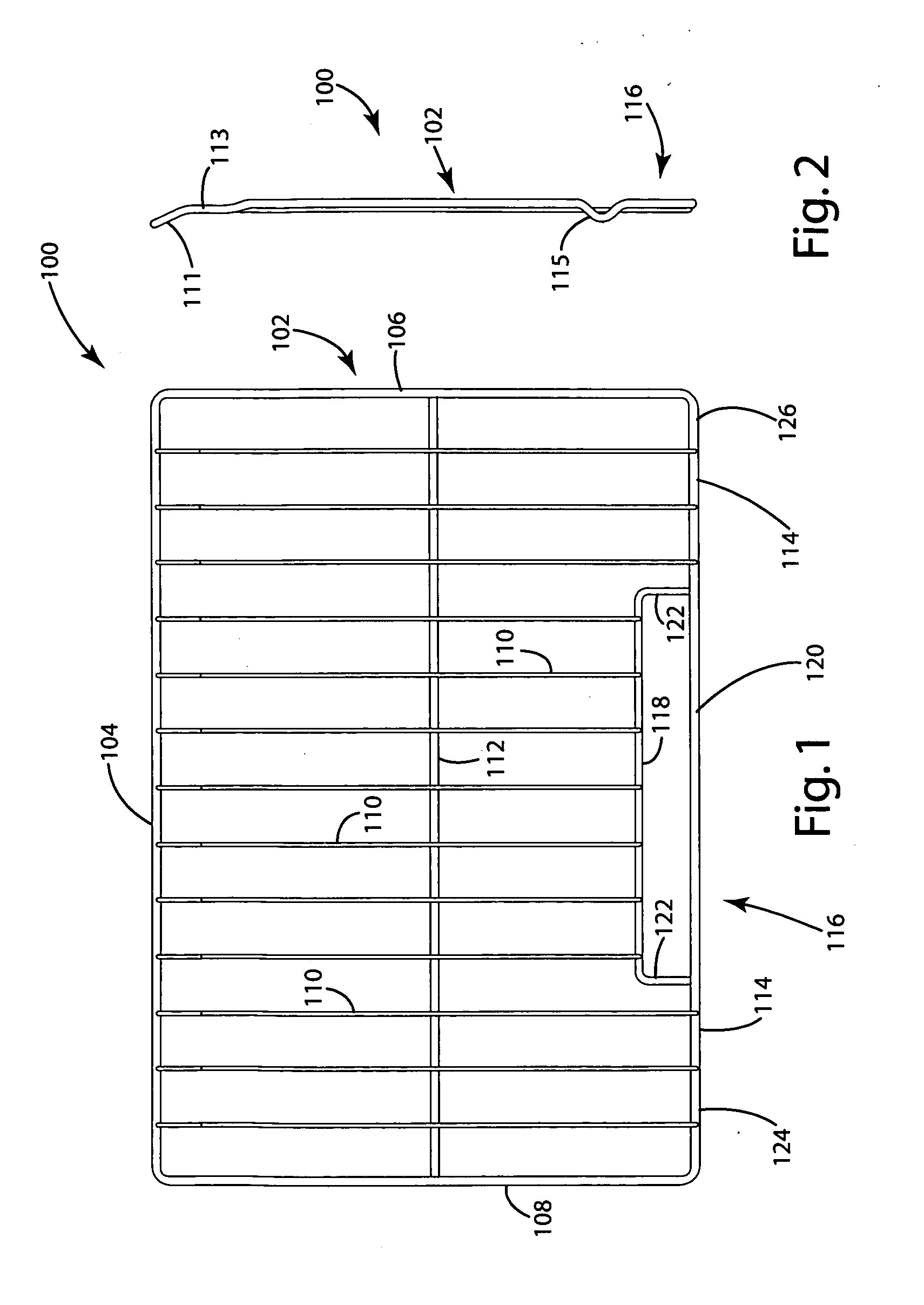
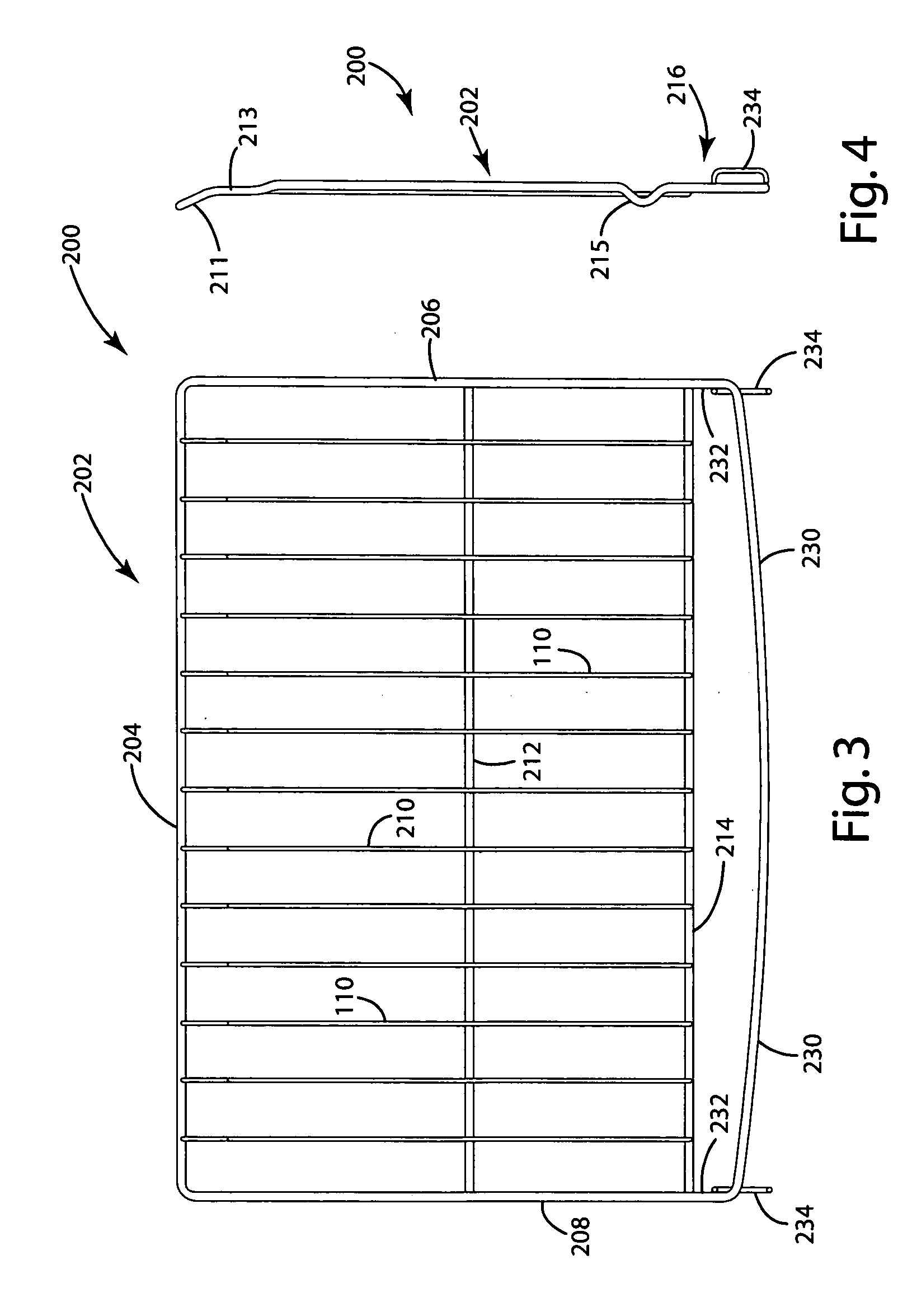
[0067]a handle rack is illustrated in FIGS. 3 and 4 as handle rack 200. The handle rack 200 includes an oven rack 202. The oven rack 202 is in part a substantially conventional oven rack, with the exception of the handle 216 as described in sub sequent paragraphs herein. as with the oven rack 102, the oven rack 202 includes an elongated rear brace 204 positioned adjacent the rear of the oven cavity when the oven rack 202 is in its retracted and normal position within the oven cavity (not shown).

[0068]Interconnected or otherwise integral with the rear brace 204 is a right brace 206 which extends perpendicular to the rear brace 204. The right brace 206 extends between the forward and rear sections of the oven rack 202, and essentially acts as a support brace for other elements of the oven rack 202. Also, when the oven rack 202 is placed within the oven cavity, the right brace 206 will typically rest or otherwise be releasably secured on a rib or other conventional element of the oven ...

fourth embodiment

[0076]a handle is illustrated as handle 400 in FIGS. 7 and 8. In this configuration, the handle 400 includes a curved front handle brace 402 having side portions 404, 406. The front handle brace 402 has a curved configuration that extends across the entirety of the width of an interconnected oven rack (not shown). The side portions 404, 406 may be interconnected to or otherwise integral with the front handle brace 402 and / or left and right side braces of the interconnected oven rack. Also, the side portions 404, 406 and the front handle brace 402 may be angled downwardly as illustrated in FIG. 8. Still further, the handle 400 may include a front brace 408 positioned rearwardly of the front handle brace 402. The front brace 408 may provide a bracing and supporting means for interconnected support members of the oven rack (not shown).

fifth embodiment

[0077]a handle rack is illustrated as handle rack 500 in FIGS. 9 and 10. The handle rack 500 has a configuration which is similar to the handle rack 100 illustrated and described herein with respect to FIGS. 1 and 2. More specifically, the handle rack 500 includes an oven rack 502 with a handle 516. The oven rack 502 includes an elongated rear brace 504, positioned adjacent the rear of the oven cavity when the oven rack 502 is in its retracted and normal position. Interconnected to or otherwise integral with the rear brace 504 is a right brace 506 extending perpendicular to the rear brace 504. The right brace 506 extends between the forward and rear sections of the oven rack 502, and essentially acts as a support brace for other elements of the oven rack 502. Also, when the oven rack 502 is placed within the oven cavity, the right brace 506 will typically rest or otherwise be releasably secured on a rib or other conventional element of the oven cavity. The oven rack 502 also include...


PUM


Abstract

An oven rack assembly (1000) includes an oven rack (1008) and a slide system (1018). The slide system (1018) includes slide devices (1020) positioned at opposing sides of the oven rack (1008). A subframe (1040) is positioned below the slide devices (1020). Retention / release devices (1062) are mounted on the slide devices (1020) and are manually operable by a user so as to selectively retain the subframe (1040) in a stationary position or, alternatively, release the subframe (1040) so that the subframe (1040) can be removed from the oven (128′).

Description

CROSS-REFERENCE TO RELATED APPLICATIONS[0001]This application is a continuation-in-part of International Patent Application PCT / US2006 / 045831 filed Nov. 30, 2006.STATEMENT REGARDING FEDERALLY SPONSORED RESEARCH OR DEVELOPMENT[0002]Not applicable.REFERENCE TO A MICROFICHE APPENDIX[0003]Not applicable.BACKGROUND OF THE INVENTION[0004]1. Field of the Invention[0005]The present invention relates to oven products and, more particularly, to oven rack assemblies having release mechanisms for releasing oven sub-frames from oven liners, and rearwardly positioned catches for capturing the sub-frames.[0006]2. Background Art[0007]Various types of oven racks are well known in the industry. For example, steel wire oven racks are often manufactured from a steel rod which is drawn, so as to form steel wire. These oven racks formed of steel wire products can be coated with various types of materials. Also, oven racks and other oven-related articles can be manufactured from products other than steel....

Claims


Application Information

Patent Timeline
Patent Type & Authority Applications(United States)
IPC IPC(8): F24C15/16
CPCF24C15/168F24C15/16A47B55/02A47L15/507
Inventor STEWART, BRIAN J.AMBROSE, I, JEFFREY ALANYOCHUM, JASON ROBERT
Owner SSW ADVANCED TECH LLC
Why Eureka
Try Eureka