Circular surgical stapling instrument with anvil locking system

a technology of locking system and surgical stapler, which is applied in the direction of surgical staples, surgical forceps, applications, etc., can solve the problems of increasing the difficulty of user, achieving the desired amount of tissue compression, and presenting additional challenges to the user

Active Publication Date: 2010-09-23
CILAG GMBH INT
View PDF99 Cites 276 Cited by
  • Summary
  • Abstract
  • Description
  • Claims
  • Application Information

AI Technical Summary

Benefits of technology

[0010]The invention overcomes the above-noted and other deficiencies of the prior art by providing a surgical stapling instrument for applying one or more surgical staples to tissue. Various embodiments comprise a handle assembly and a shaft assembly that is coupled to the handle assembly. A stapling head assembly may be operably coupled to the shaft assembly. The stapling head assembly may comprise a staple cartridge for supporting one or more surgical staples, a staple driver for engaging and driving the staples from the staple cartridge, and a knife that is movably supported in the stapling head assembly. The surgical stapling instrument may further include a drive system for applying drive motions to the staple driver and the knife. An anvil is movably supported relative to the staple cartridge for axial movement toward and away from the staple cartridge. The instrument may also include an anvil adjustment assembly for selectively adjusting an axial position of the anvil relative to the staple cartridge. The instrument also comprises an anvil locking system configured to cooperate with the anvil adjustment assembly to selectively lock and unlock the anvil in axial position relative to the staple cartridge.
[0011]In another general aspect of the present invention, there is provided a surgical stapling instrument for applying one or more surgical staples to tissue. Various embodiments may comprise a handle assembly and a stapling head assembly that is operably coupled to the handle assembly. An anvil is movably supported relative to the stapling head assembly for selective axial travel toward and away from the stapling head assembly. An anvil adjustment assembly is supported by the handle assembly for selectively adjusting an axial position of the anvil relative to the staple cartridge. An anvil locking system is configured to cooperate with the anvil adjustment assembly to selectively lock and unlock the anvil in axial positions relative to the stapling head.

Problems solved by technology

Previously, this surgical procedure was a laborious and time consuming operation.
Achieving a desired amount of tissue compression becomes challenging when dealing with thick tissues and thin tissues.
Such devices, however, present additional challenges to the user.
Those anvil systems that are compliant in nature may facilitate undesirable movement or deflection of the anvil during firing which could adversely affect proper staple formation.

Method used


Image

  • Circular surgical stapling instrument with anvil locking system
  • Circular surgical stapling instrument with anvil locking system
  • Circular surgical stapling instrument with anvil locking system

Examples


Embodiment Construction

[0024]Certain exemplary embodiments will now be described to provide an overall understanding of the principles of the structure, function, manufacture, and use of the devices and methods disclosed herein. One or more examples of these embodiments are illustrated in the accompanying drawings. Those of ordinary skill in the art will understand that the devices and methods specifically described herein and illustrated in the accompanying drawings are non-limiting exemplary embodiments and that the scope of the various embodiments of the present invention is defined solely by the claims. The features illustrated or described in connection with one exemplary embodiment may be combined with the features of other embodiments. Such modifications and variations are intended to be included within the scope of the present invention.

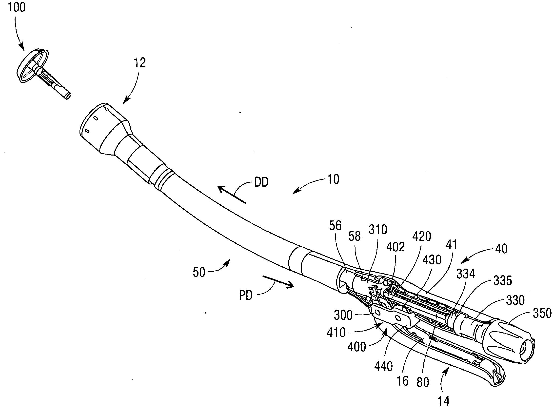
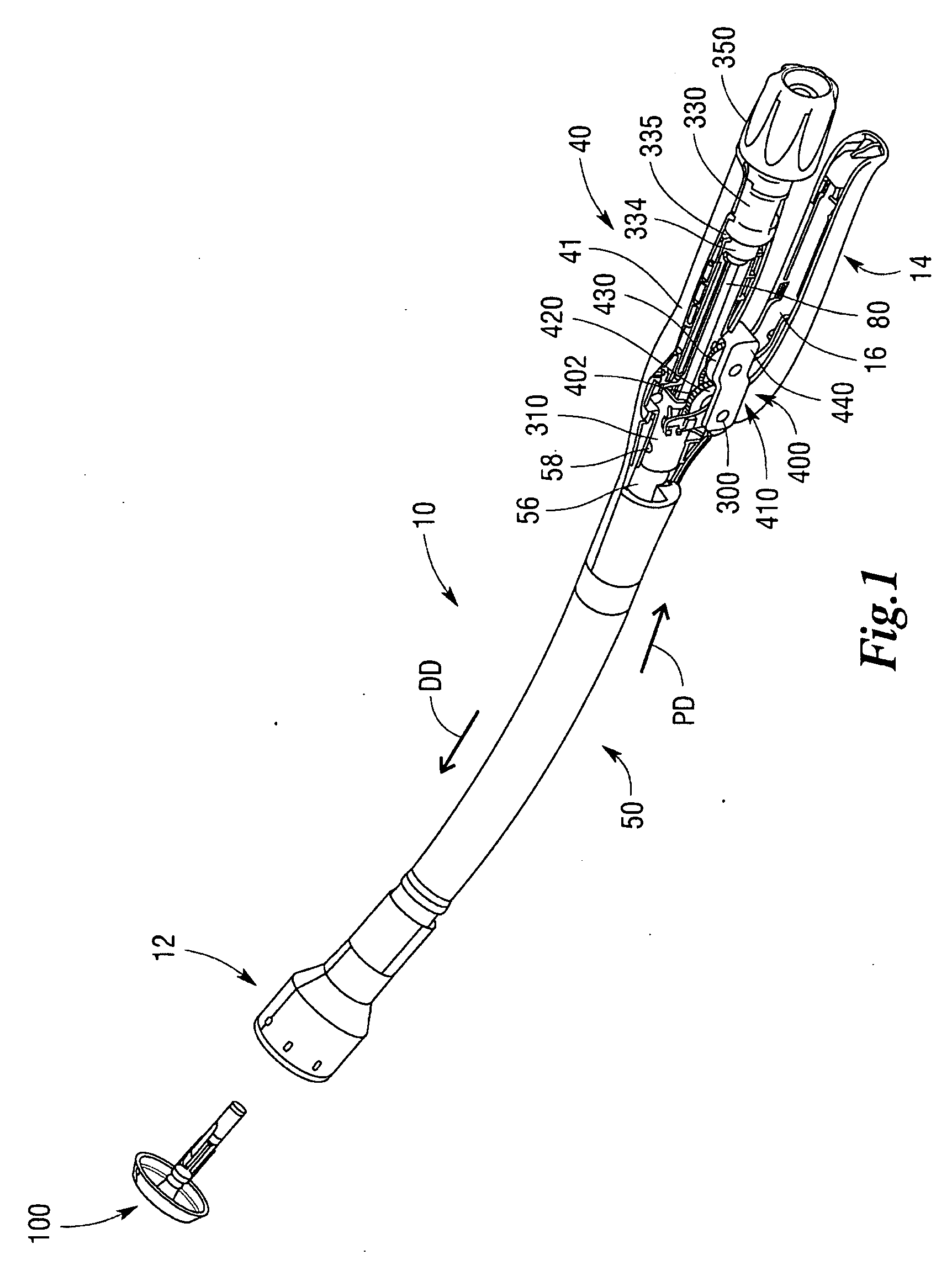
[0025]Turning to the Drawings, wherein like numerals denote like components, there is shown a circular stapler 10 that includes a unique and novel system for locki...


PUM

PropertyMeasurementUnit
forcesaaaaaaaaaa
force measurementaaaaaaaaaa
compression forceaaaaaaaaaa

Abstract

Circular stapling instruments for cutting and applying one or more surgical staples to tissue are disclosed. The instruments include various forms of anvil locking systems designed to selectively prevent the anvil from moving axially relative to the stapling head of the stapling instrument. One embodiment employs an elongated gear rack that is selectively engagable with locking gears to prevent axial motion of the elongated gear rack and an adjustment shaft used to axially position the anvil. Other embodiments employ a gear assembly that cooperates with the elongated gear rack. A locking member is movably supported by a handle assembly that houses the gear assembly and elongated gear rack. The locking member is configured for selective meshing engagement with the gear assembly to ultimately prevent axial movement of the gear rack and adjustment shaft.

Description

FIELD OF THE INVENTION[0001]The present invention generally relates to surgical staplers, and more particularly, to an anvil locking system for locking an anvil of a circular stapling instrument in place.BACKGROUND[0002]In certain types of surgical procedures, the use of surgical staples has become the preferred method of joining tissue and, as such, specially configured surgical staplers have been developed for these applications. For example, intra-luminal or circular staplers have been developed for use in a surgical procedure known as an anastomosis. Circular staplers useful for performing an anastomosis are disclosed, for example, in U.S. Pat. Nos. 5,104,025; 5,205,459; 5,285,945; and 5,309,927 which are each herein incorporated by reference in their respective entireties.[0003]One form of an anastomosis comprises a surgical procedure wherein sections of intestine are joined together after a diseased portion has been excised. The procedure requires re-joining the ends of the tw...

Claims


Application Information

Patent Timeline
Patent Type & Authority Applications(United States)
IPC IPC(8): A61B17/068
CPCA61B17/072A61B17/115A61B17/1155A61B2019/464A61B19/46A61B2017/07257A61B2017/2923A61B17/32053A61B90/06A61B2090/064
Inventor MEASAMER, JOHN P.TSONTON, MARKMOLITOR, NICHOLAS G.JAMISON, BARRY T.KILLINGER, SCOTT B.KOPLIN, RANDALL S.CHIN, WAI N.
Owner CILAG GMBH INT
Why Eureka
Try Eureka