Pipe joint restraint

a technology for reducing which is applied in the direction of sleeve/socket joints, fluid pressure sealed joints, bends, etc., can solve the problems of joint failure, leakage and property damage, and the tendency of joints and fittings to move, so as to reduce the tilting or canting of the joined parts, and the relative movement or tilting of the joined parts.

Active Publication Date: 2010-09-30
RELIANCE WORLDWIDE CORP
View PDF26 Cites 20 Cited by
  • Summary
  • Abstract
  • Description
  • Claims
  • Application Information

AI Technical Summary

Benefits of technology

[0020]At least one additional strap having opposing ends each having one of fifth and sixth pipe connectors may be provided, in which case the method includes connecting the fifth pipe connector to the third adjacent pipe section and the sixth pipe connector to the pipe fitting. The method may also include providing one of the adjacent pipe sections as a blind end, in which case the method includes connecting the fourth pipe connector adjacent an outlet of the pipe fitting leading to the blind end and placing the second strap so it crosses the blind end and the fourth pipe connector. The method may include providing each of the pipe connectors as a clamp encircling the pipe, with at least one end of each strap having an adjustable fastener to vary the length and tightness of the strap to which the adjustable fastener is connected.
[0024]Preferably, each end of the straps connects to one of the pipe connectors adjacent to a distal end of the sleeve on that pipe section. Optionally, each end of the straps connects to a different one of the pipe connectors with the connectors encircling a distal end of the sleeve to further seal against leakage. Each end of the outer strap is preferably connected to the pipe connectors that are closer to the curved pipe section.
[0026]Further variations are provided which use T fittings and Y fittings, each having various adjacent pipe sections or additional pipe fittings connected by sealing tubes and clamps. In each variation, a strap extends across the joint to fasten the adjacent pipe section or pipe fitting to the main fitting or to an adjacent pipe section in order to restrain relative movement or tilting of the joined parts. Those straps or are held to the respective parts by pipe connectors that preferably clamp the ends of the straps to the respectively joined and restrained parts by an adjustable tightening mechanism. Preferably, the length of the straps can be changed to tighten the straps and urge the joined parts of the pipe joint toward each other. Ideally, the straps are symmetrically placed on diametrically opposing sides of the pipe sections and joints to reduce tilting or canting of the joined parts.

Problems solved by technology

However, under “high” pressures, e.g., above 15-20 psi, such as might occur within the piping system when drains become blocked in a multi-story building or under system pressure testing, these joints and fittings have a tendency to move and sometimes separate, with resulting leakage and property damage.
At least in part because gravity (the weight of the pipe) does not effectively counter the separation forces where the pipe is running horizontally, such joint failures tend to occur at or near the point where the drain piping changes direction from vertical to horizontal, particularly as commonly occurs at the base of a multi-story vertical “stack” of pipe, such as at the building ground floor.
Where the joints at such transitions are able to withstand the pressure and maintain integrity, however, the next and subsequent joints in the horizontal piping at which changes in direction occur may also be subject to the same type of failure.
There is no standard solution to this, and not every building contractor takes the pains to address it.

Method used


Image

  • Pipe joint restraint
  • Pipe joint restraint
  • Pipe joint restraint

Examples


Embodiment Construction

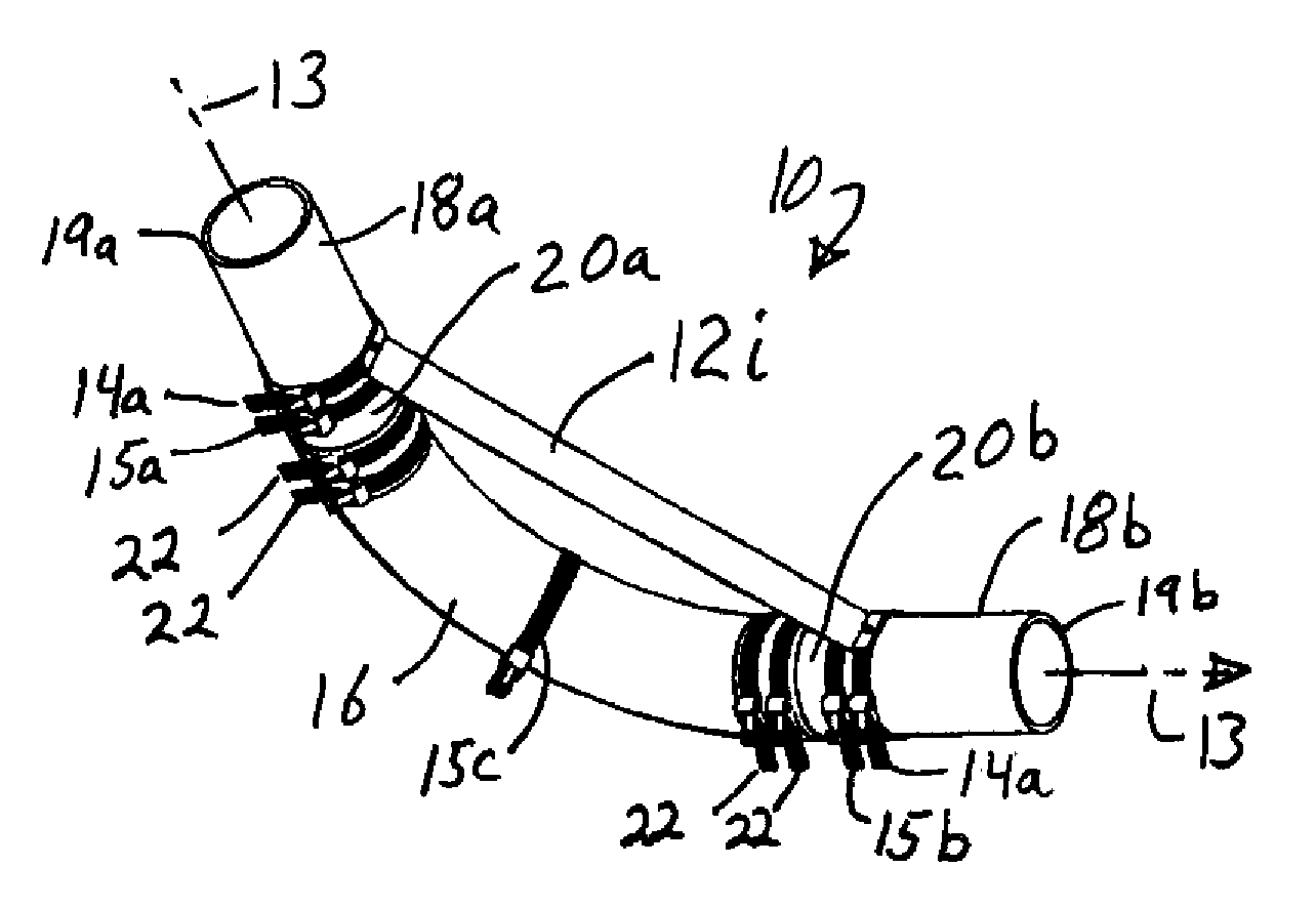
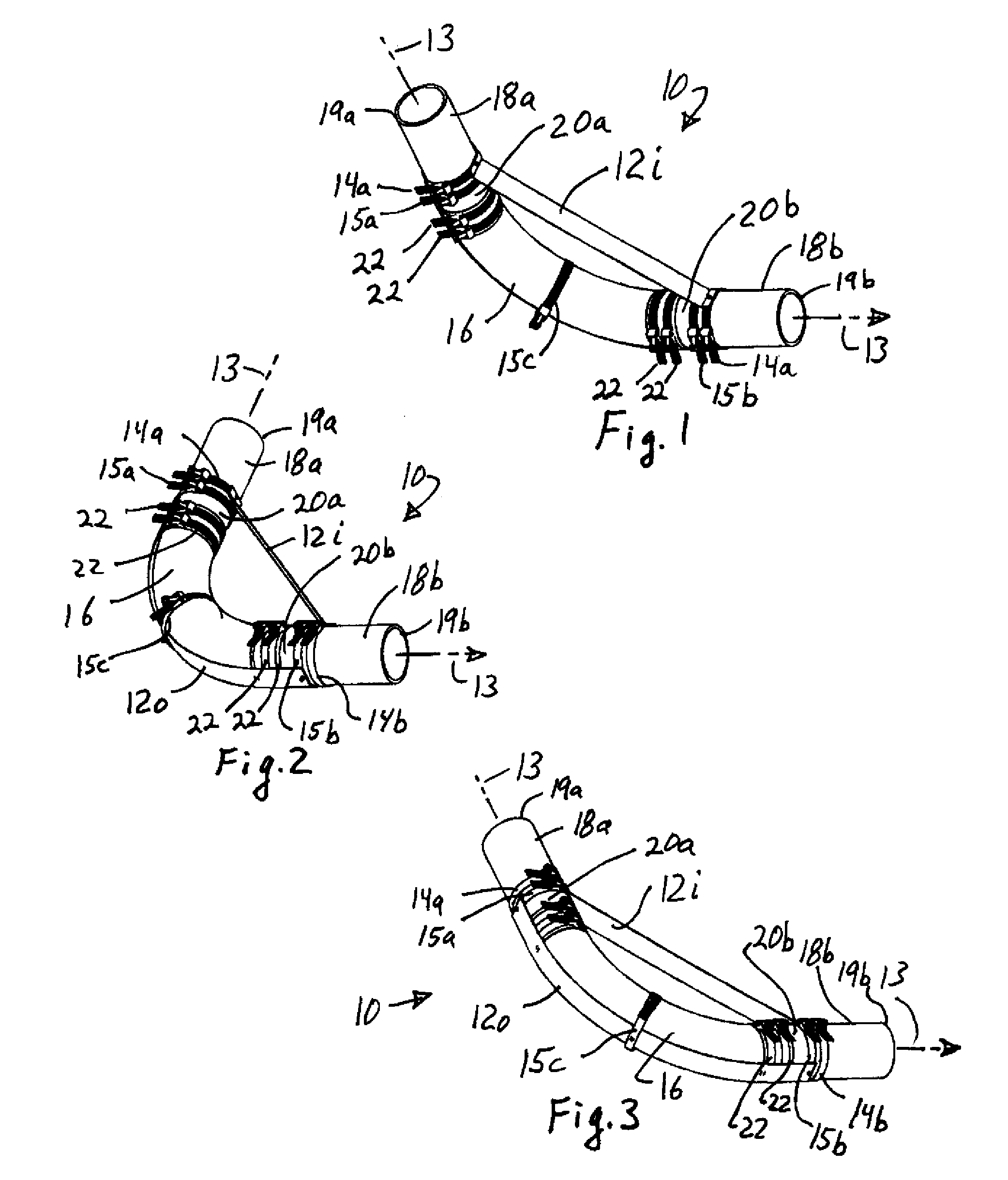
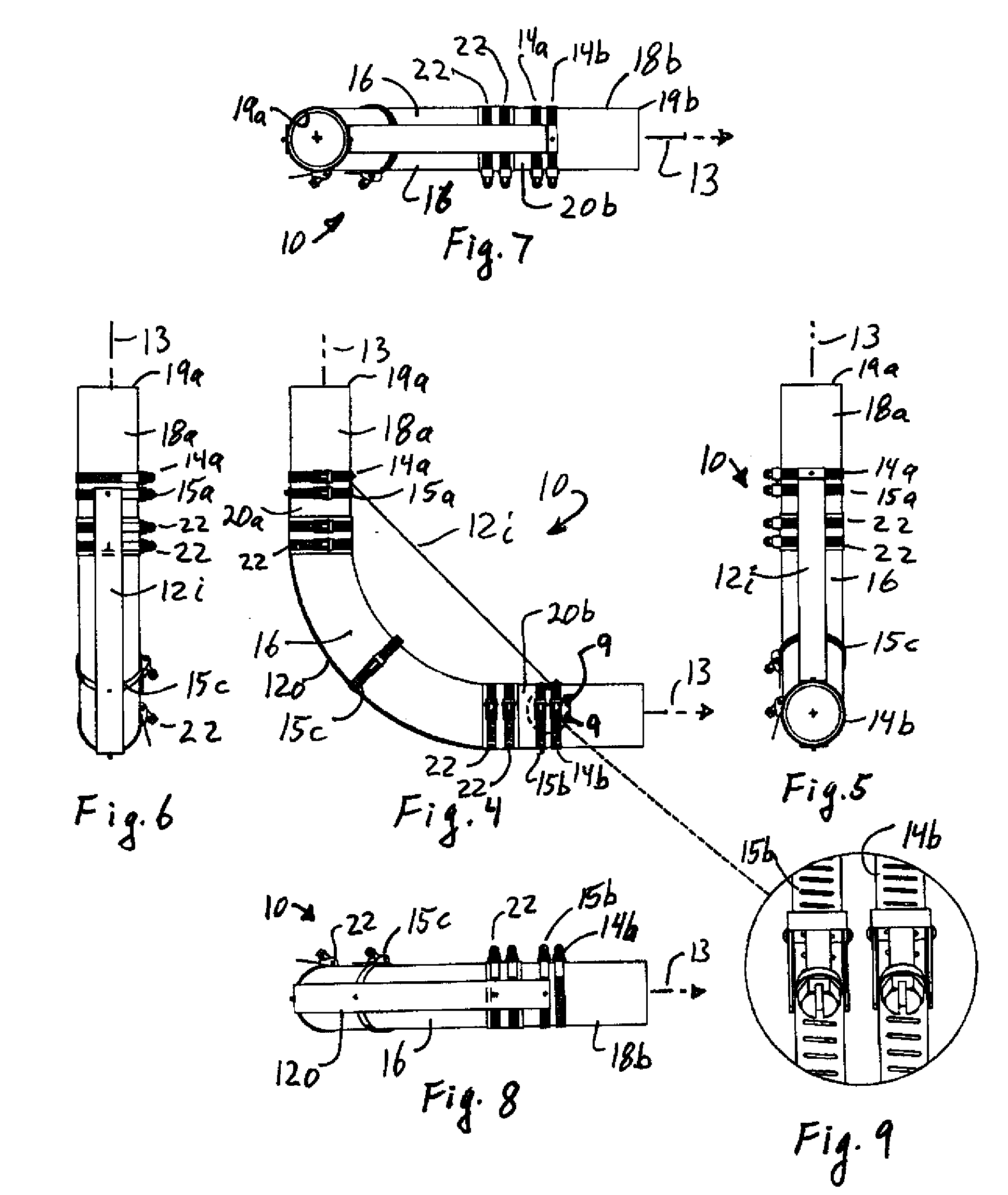
[0075]Referring to FIGS. 1-9 and 11-12, a pipe restraint 10 is shown having elongated inner and outer straps 12i and 12o, respectively. Pipe connector 14a, 14b are fastened to opposing ends of inner strap 12i, and pipe connectors 15a, 15b are fastened at opposing ends of the outer strap 12o. An additional pipe connector 15c can be fastened to the outer strap 12o intermediate the ends of the strap as shown in FIG. 1. The pipe restraint 10 helps prevent a pipe joint from coming apart under high fluid flows through the pipe along flow path 13 through the pipe, or under high internal pressures in the pipe.

[0076]A typical pipe joint includes a curved pipe section 16, such as an elbow section having a 45° or a 90° curve, with opposing ends 17a, 17b (FIG. 20). The typical joint further has a first upstream pipe section 18a and a second downstream pipe section 18b on opposing ends of curved pipe section 16. Each pipe section 18a, 18b has a first upstream end 19a and a second downstream end ...


PUM


Abstract

A joint restraint is provided for a curved pipe joint having a curved pipe section joining two adjacent pipe sections. The pipes are joined using tubular sleeves held by hose clamps to form fluid tight seals, with two clamps on each end of the curved pipe sections and two clamps on each proximal end of the adjacent pipe sections. An inner strap extends between and fastens to one of the clamps on each adjacent pipe section forming a chord of an arc. An outer strap extends along an outer periphery of the joined pipes and fastens to the other clamps on each adjacent pipe section. The straps are in a plane through a center of the flow path of the joined pipes

Description

CROSS-REFERENCE TO RELATED APPLICATIONS[0001]Application claims priority to Provisional Patent Application No. 61 / 163,398 filed Mar. 25, 2009, the complete contents of which are incorporated herein by reference.BACKGROUND[0002]This application claims the benefit of provisional application Ser. No. 61 / 163,398 filed Mar. 25, 2009, the complete contents of which are incorporated herein by reference.[0003]This invention relates to a method and device that helps maintain the integrity of a pipe system when subjected to abnormal internal pressures. It is especially useful in drain pipe systems made of cast iron.[0004]In a typical building drain piping system, sections of cast iron drain or DWV (drain, waste and vent) pipe and their fittings are assembled by butting the ends of the pipe sections together and bridging the joints with water-tight rubber or rubber / metal couplings. These abutting pipes and fittings are secured together and sealed with metal band screw clamps tightened to about...

Claims


Application Information

Patent Timeline
Patent Type & Authority Applications(United States)
IPC IPC(8): F16L17/00
CPCF16L43/02F16L21/065F16L35/00F16L55/00
Inventor O'NEIL, VIRGIL E.LESTAGE, JAMES F.
Owner RELIANCE WORLDWIDE CORP
Why Eureka
Try Eureka