Retrofittable Bend Strain Relief With A Latching Ring

a technology of latching ring and strain relief, which is applied in the field of cable connectors, can solve the problems of affecting the signal transmission capability of the fiber, bending or kinking of the inner buffered fiber of the cable, and affecting the delicateness of the optical fiber cable,

Active Publication Date: 2010-09-30
MOLEX INC
View PDF4 Cites 121 Cited by
  • Summary
  • Abstract
  • Description
  • Claims
  • Application Information

AI Technical Summary

Benefits of technology

[0005]However, a particular disadvantage of most known right-angled booted connectors is that the boots must be placed into position on the cable before the cable is attached to the other device and before the cable is routed to its ultimate destination. This causes problems in routing the cable through ductwork or conduit. In addition, further rerouting of the cable is difficult with the boots attached.
[0017]An additional advantage of the present bend limiter is that in certain configurations it may be removed or reattached as necessary even when the cable is connected to an end device or after the cable has been rerouted. Because the bend limiter system is retrofittable, the need for the installer or end user to disconnect the cable is eliminated, which helps reduce or eliminate service disruptions. Unnecessary mating and demating cycles that possibly could damage the end faces of the fiber are also eliminated.
[0005]However, a particular disadvantage of most known right-angled booted connectors is that the boots must be placed into position on the cable before the cable is attached to the other device and before the cable is routed to its ultimate destination. This causes problems in routing the cable through ductwork or conduit. In addition, further rerouting of the cable is difficult with the boots attached.

Problems solved by technology

Optical fiber cables are somewhat delicate in that they can be bent or kinked and damage or destroy the interior buffered fiber of the cable.
Overstressing or kinking can interfere with the signal transmitting capabilities of the fiber.
However, it is not always possible to extend the cable in a straight line, particularly when the cable is used in compact environments.
However, a particular disadvantage of most known right-angled booted connectors is that the boots must be placed into position on the cable before the cable is attached to the other device and before the cable is routed to its ultimate destination.
This causes problems in routing the cable through ductwork or conduit.
In addition, further rerouting of the cable is difficult with the boots attached.

Method used


Image

  • Retrofittable Bend Strain Relief With A Latching Ring
  • Retrofittable Bend Strain Relief With A Latching Ring
  • Retrofittable Bend Strain Relief With A Latching Ring

Examples


Embodiment Construction

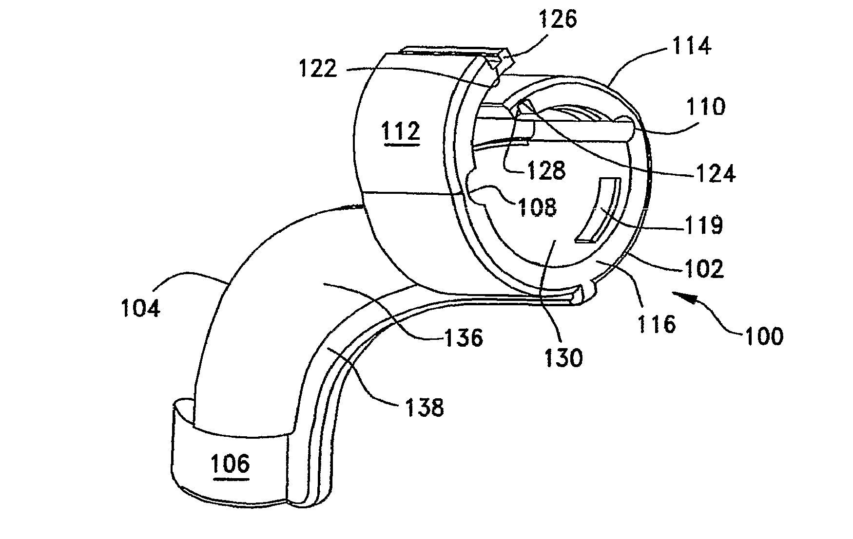
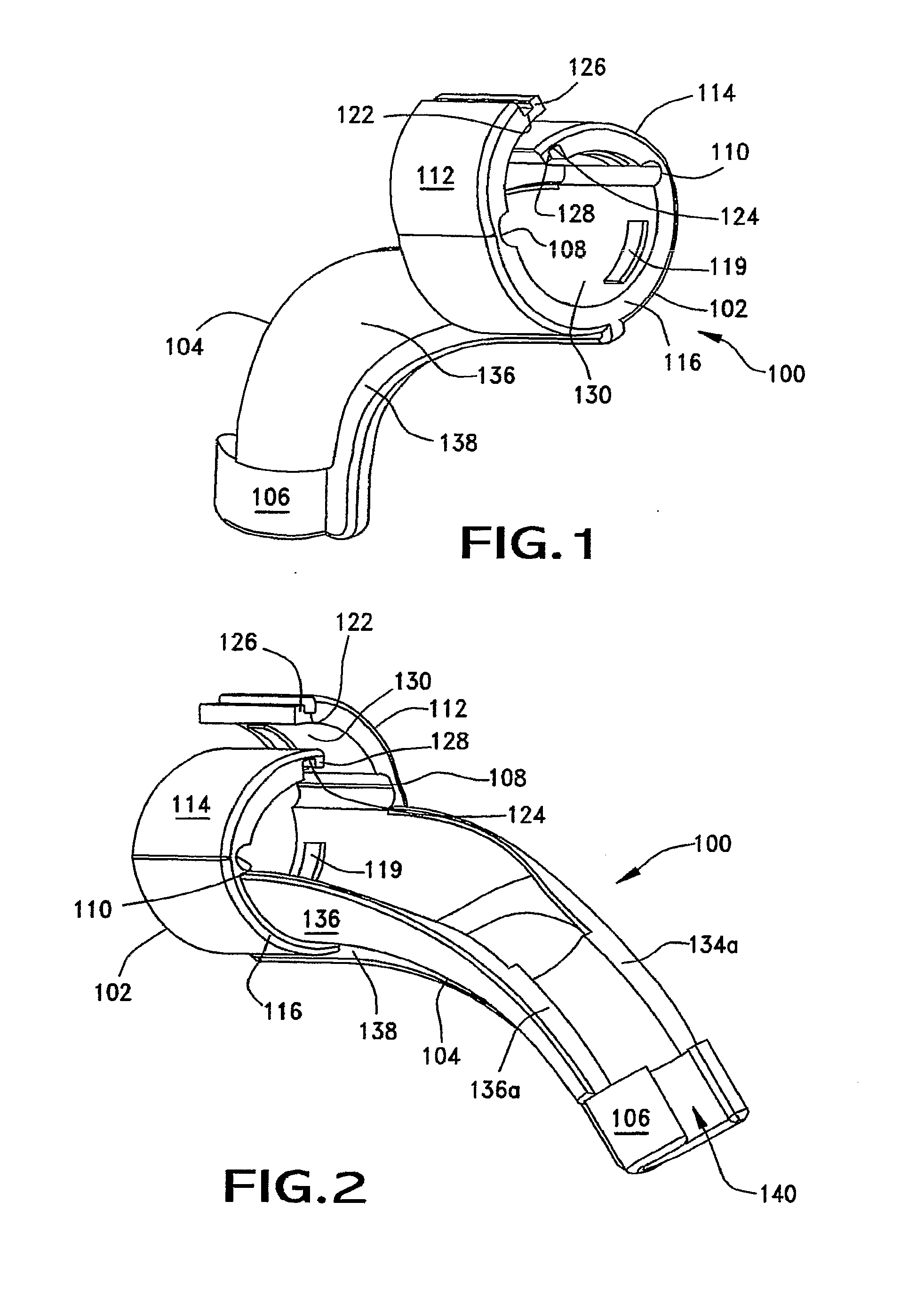
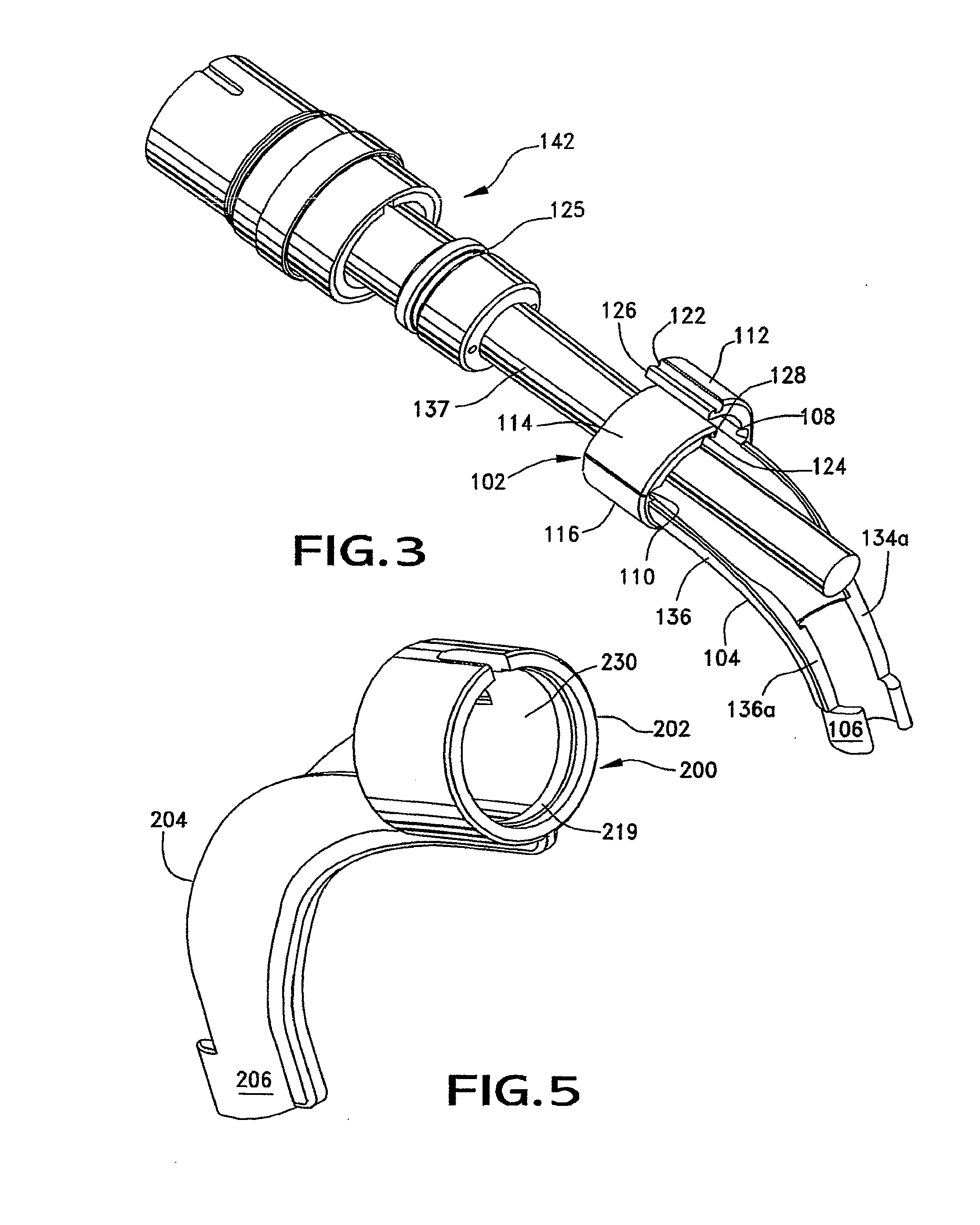
[0015]In order to address the need for reducing or eliminating damage to delicate optical fibers and yet allowing for the convenient routing of cables, strain relief of fiber optic cables is accomplished as follows: A bend limiting system, which may be retrofit onto a cable connector, is installed over the mating face of the connector that connects to another cable or device. Because of the ability of the bend limiting system to be retrofit onto connectors at any time, the bend limiter may be placed into position after the cable has been routed and either before or after the connector is installed into the end device.

[0016]A particular advantage of the present system is that a cable installer or end user is able to easily and quickly route and reroute cabling through ductwork and conduit without worrying that the bend limiter will potentially snag or get stuck to the end of the conduit or become entangled with other cables.

[0017]An additional advantage of the present bend limiter is...


PUM


Abstract

A bend limiting system (strain relief (200)) that may be retrofit onto a cable connector (142). The bend limiting system includes a latching ring (102) configured to fit over the cable connector's mating face so that the bend limiting system may be placed into position after the connector is connected to another device. The bend limiter (200) includes three sections. These sections include a latching ring (202) in the front, an elongated cable guide (204) in the middle and a cable retainer (206) at the end. The latching ring portion (202) is of a generally circular shape to engage the mating face of a round complementary connector.

Description

FIELD OF THE INVENTION[0001]This invention generally relates to cable connectors and, more particularly, to a strain relief system for connectors such as optical fiber connectors.BACKGROUND OF THE INVENTION[0002]Connectors are used for joining light-transmitting optical fiber cables to transmitter devices, receiver devices or to other cables. Optical fiber cables are somewhat delicate in that they can be bent or kinked and damage or destroy the interior buffered fiber of the cable. Therefore, as an optical fiber cable projects away from a connection, it is important that the fiber project in a manner that will not overstress or kink the fiber. Overstressing or kinking can interfere with the signal transmitting capabilities of the fiber.[0003]Typically, the best condition for an optical fiber cable is to project straight away from its connection. However, it is not always possible to extend the cable in a straight line, particularly when the cable is used in compact environments. For...

Claims


Application Information

Patent Timeline
Patent Type & Authority Applications(United States)
IPC IPC(8): G02B6/38
CPCG02B6/3829G02B6/4478G02B6/3887G02B6/38875
Inventor SZILAGYI, B. DANIEL
Owner MOLEX INC
Why Eureka
Try Eureka