Fixing devices and stabilization systems using said fixing devices

a technology of fixing devices and fixing devices, which is applied in the field of fixing devices and stabilizing systems using said fixing devices, can solve the problems of paralysis of patients, damage or lack of purchase, and difficulty in using such hooks, and achieve the effect of limited and controlled relative mobility

Active Publication Date: 2010-09-30
ZIMMER SPINE INC
View PDF83 Cites 68 Cited by
  • Summary
  • Abstract
  • Description
  • Claims
  • Application Information

AI Technical Summary

Benefits of technology

[0013]A first object of the present invention is to provide a fixing device for connecting a linking member to a bone, more particularly, a vertebra, and which allows a limited and controlled relative mobility between the vertebra and the linking member.

Problems solved by technology

However, using such hooks can be difficult because their use increases the risk that the physician (or other operative) might contact and potentially damage the spinal cord that extends along the centre of the spinal canal (which can result in paralysis of the patient).
Using a screw and rod system reduces this risk, but has other drawbacks.
However, the screws are inserted into the pedicles of the vertebrae, which in some cases are small or are deteriorated and can be damaged or do not provide sufficient purchase to permanently hold the screw.
However, the manufacturing of such elastically deformable linking members is rather expensive and the type of mobility allowed by such linking members is not adapted to all situations.

Method used


Image

  • Fixing devices and stabilization systems using said fixing devices
  • Fixing devices and stabilization systems using said fixing devices
  • Fixing devices and stabilization systems using said fixing devices

Examples


second embodiment

[0085]FIGS. 4 to 7B show the fixing device.

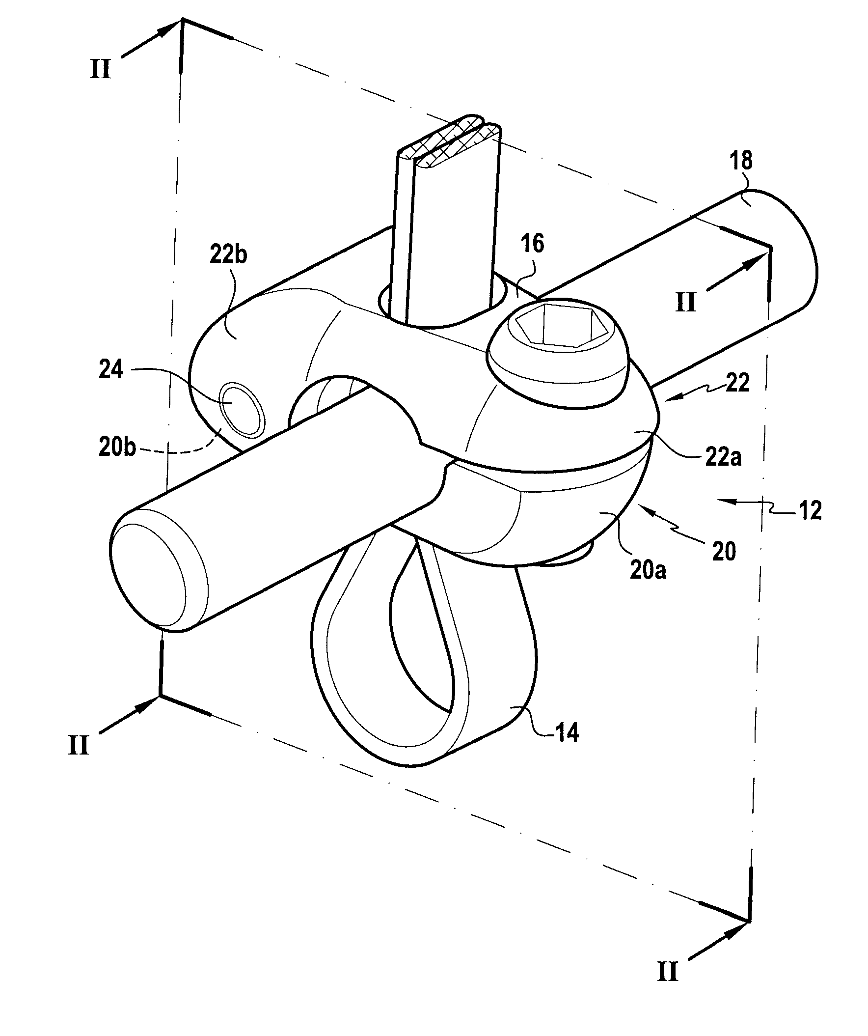
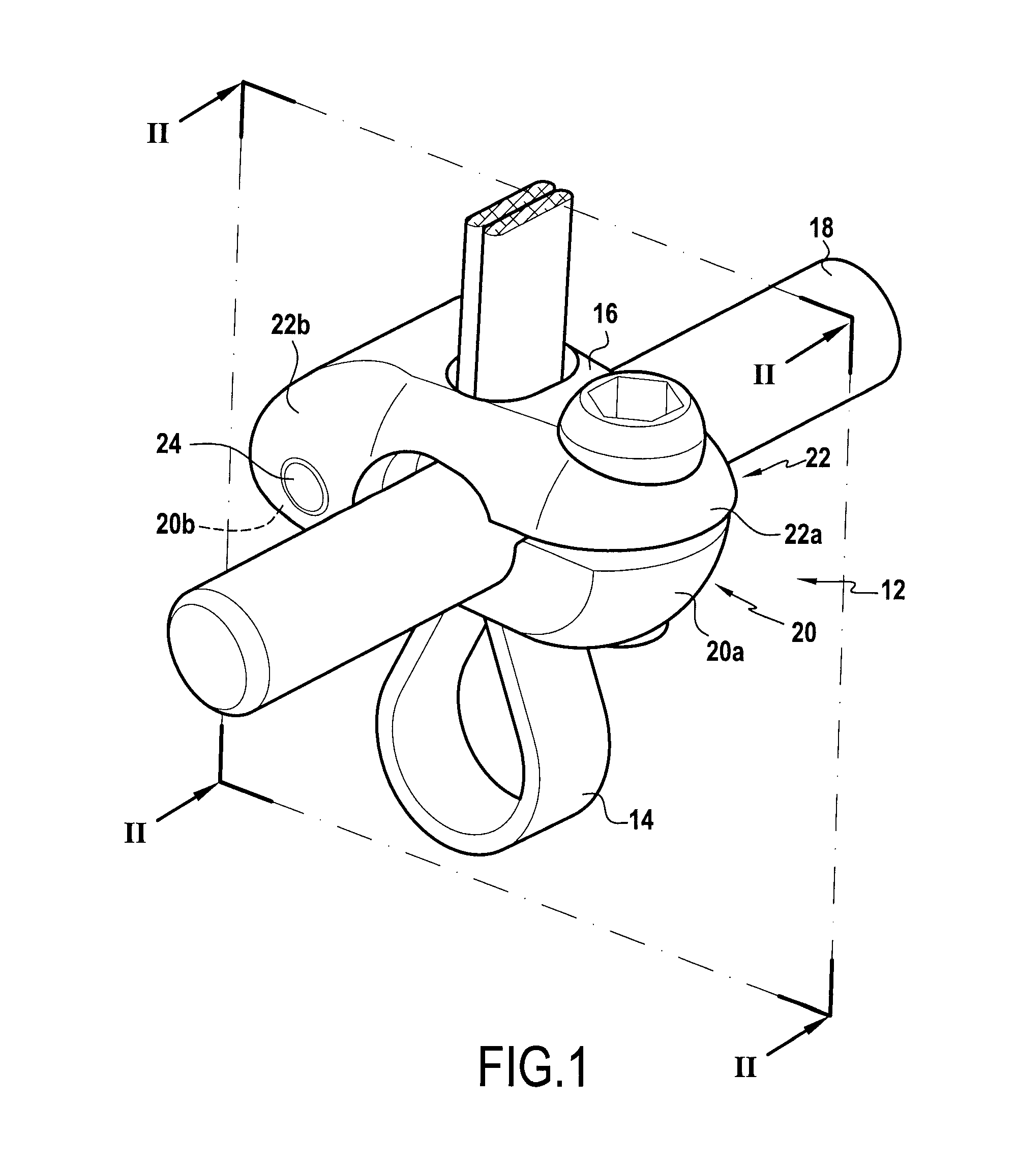
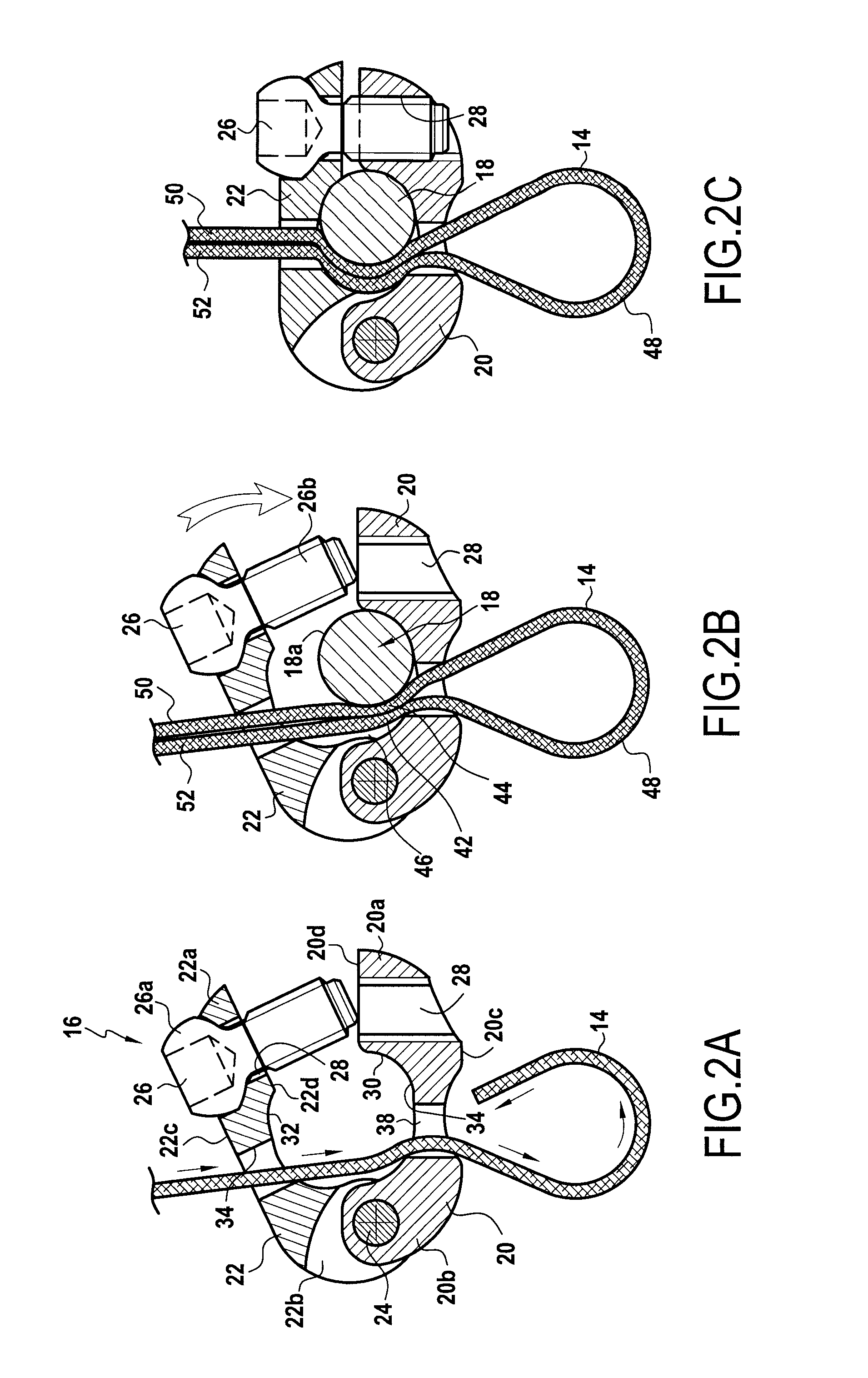
[0086]In these figures, there can be seen the rod 18, the connecting part now referenced 12′, and the flexible ligature 14.

[0087]In this embodiment, the connecting part 12′ is constituted by a part 50 that is generally U-shaped. The inside wall of this part is constituted by a bottom 52 of substantially semi-cylindrical shape and by two substantially plane portions 54 and 56 that correspond to the two limbs of the part 50. The width w of the recess 58 formed in the part 50 is substantially equal to the diameter d of the rod 18. On its outside face 50a which is circularly symmetrical about a longitudinal axis of the part 50, there is provided a thread 60 occupying its upper portion. The thread 60 is located entirely above the rod 18 when it is put into place in the recess 58.

[0088]The thread 60 is designed to co-operate with a clamping ring 62 that constitutes the adjustable locking means. This ring has a slightly frusto-conical bore 64 with...

first embodiment

[0092]In the configuration shown in FIG. 7B, the middle strands 42 and 44 of the flexible ligature 14 are disposed respectively one in each of the passageways 76 and 78, i.e. on either side of the rod 18. This configuration likewise presents all of the advantages described with reference to the device since the free ends 50 and 52 of the ligature 14 are accessible for exerting the desired traction in order to obtain suitable clamping on the spinous process prior to locking the clamping ring 62 on the part 52.

[0093]This second embodiment presents the advantage of being simpler in design since it serves in particular to avoid making two longitudinal parts constituting a kind of clamp hinged on the pin 24.

[0094]It is to be underlined that this second embodiment allows obtaining the same relative mobility between the connecting part 12′ and the bone, especially a vertebra. Indeed, the part 50 of the connecting part 12′ has an outer face 50′. A limited portion of this outer face 50′ is p...

third embodiment

[0096]With reference to FIGS. 8 to 10, the fixing device will be described.

[0097]In this embodiment, the connecting part 12″ consists of a cylindrical sleeve tube 80 having a cylindrical central passage 82. The diameter of the passage 82 is slightly larger than the outer diameter of the rod 18′.

[0098]The wall of the sleeve 80 is provided with a threaded circular opening 84, two lateral slots 86 and 88 disposed on each side of the circular opening 84, and a central slot 90 diametrically opposed to the circular opening 84. A screw 92 forming the locking member 16 cooperates with the threaded circular opening 84. The passage 82 of the sleeve 80 is adapted to receive the rod 18 and two portions 12″a and 12″b of the ligature 14″. A median portion 94 of the ligature 14″ passes through the central slot 90 to form a loop 96. The ligature 14″ also passes through the lateral slots 86 and 88. Consequently, the two free ends 14″c and 14″d of the ligature 14″ extend outside the sleeve 80.

[0099]W...


PUM


Abstract

A fixing device to connect a bone to a linking member (18) is characterized in that it comprises; —a connecting part (12, 20, 22) to be connected to said linking member (18), having an outer face; —a conformable elongate ligature (14) cooperating with said bone suitable for securing said connecting part to said bone; said ligature applying a portion of the outer surface of the connecting part against a portion of said bone; and—adjustable locking means (46) fastened to said connecting part (12) to maintain said ligature in a state which allows a controlled relative mobility between said bone and said connecting part (12).

Description

[0001]The present invention relates to a fixing device for fixing a rod or similar linking members to a bone, especially a vertebra, and allowing a relative mobility of the linking member with respect to the bone, a stabilization system including at least one fixing device and uses of said fixing device on said stabilization system.BACKGROUND OF THE INVENTION[0002]One field of application for the invention is holding bones in a relative position, for example to aid in the healing of breaks or the positioning of bones in the treatment of spinal deformities or spinal degenerative diseases or trauma diseases, or otherwise to correct abnormal curvatures of the spine. Other bone deficiencies and abnormalities may also benefit from embodiments of the present invention.[0003]The spine is formed of superposed vertebrae, normally aligned along a vertebral axis, from the lumbar vertebrae to the cervical vertebrae, each having a posterior wall from which projects a spinous process and two late...

Claims


Application Information

Patent Timeline
Patent Type & Authority Applications(United States)
IPC IPC(8): A61B17/70A61B17/88
CPCA61B17/7001A61B17/7011A61B17/7026A61B17/7031A61B17/7032A61B17/8869A61B17/705A61B17/7053A61B17/707A61B17/8861A61B17/7041
Inventor MEUNIER, ALAINBELLIARD, KARL PIERREMINFELDE, RICHARD
Owner ZIMMER SPINE INC
Why Eureka
Try Eureka