Control of conditioned environment by remote sensor

Inactive Publication Date: 2010-09-30
CARRIER CORP
View PDF13 Cites 66 Cited by
  • Summary
  • Abstract
  • Description
  • Claims
  • Application Information

AI Technical Summary

Problems solved by technology

However, in either case, the location of the sensor is not necessarily the location where the temperature needs to be measured and controlled.

Method used


Image

  • Control of conditioned environment by remote sensor
  • Control of conditioned environment by remote sensor

Examples


Embodiment Construction

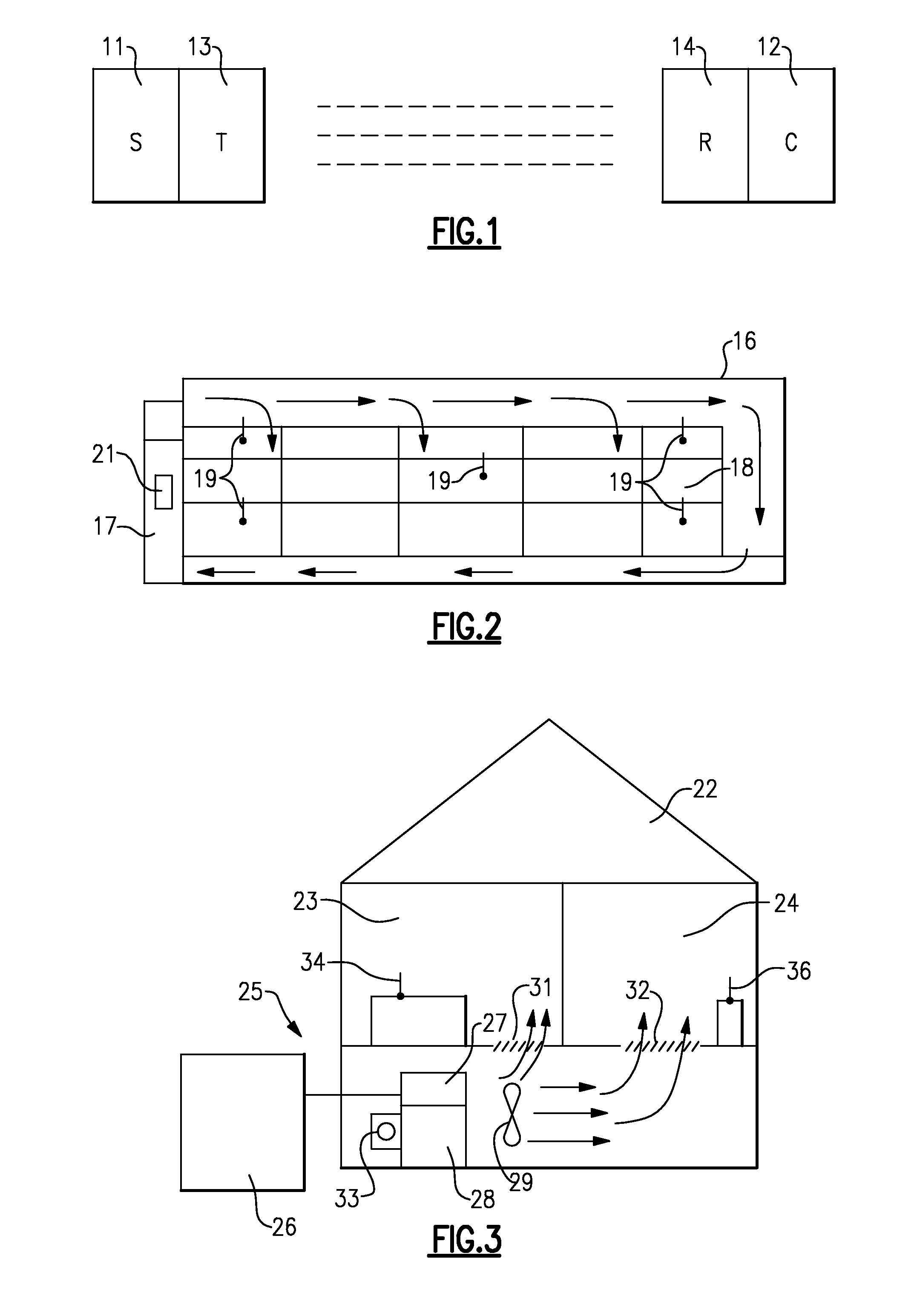
[0008]FIG. 1 shows a remote wireless sensor 11 and an associated control 12 in accordance with the present invention. The sensor 11 is designed to sense an environmental condition, such as temperature or humidity, within a space such that the control 12 can responsively operate an HVAC&R system so as to maintain that condition within a predetermined range.

[0009]In order to communicate the sensed condition to the control, the sensor 11 is provided with a transmitter 13, and the control 12 is provided with a receiver 14. The transmitter 13 and receiver 14 can be of any wireless type such as, for example, a radio frequency device. Such a wireless arrangement allows for selective placement of one or more sensors within the space to be conditioned as will now be described.

[0010]As is seen in FIG. 2, a refrigerated enclosure 16 is provided with an associated refrigeration unit 17. In transport applications, the refrigeration unit 17 is typically mounted on the front end of the refrigerate...


PUM


Abstract

A comfort HVAC or refrigeration system includes a remote sensor for sensing an environmental condition within a climate-controlled space and having, an associated transmitter for sending, a wireless signal to a receiver of a controller such that the controller can then responsively modulate the operation of the components of the HVAC or refrigeration system to maintain a desired condition at a specific location or locations within the-climate-controUed'space. The desired condition can be, for instance, temperature, humidity and / or carbon dioxide level.

Description

TECHNICAL FIELD[0001]This invention relates generally to comfort HVAC (heating, ventilation, air conditioning) and refrigeration systems and, more particularly, to a method and apparatus for maintaining desired parameters, such as temperature and humidity, within a climate-controlled space while using remote wireless sensors.BACKGROUND OF THE INVENTION[0002]Heating, ventilation, air conditioning and refrigeration (HVAC&R) systems are designed to maintain predetermined conditions in a space. These conditions are primarily related to a desired temperature range, but other conditions, such as humidity level and carbon dioxide content, for example, may be controlled as well. This is generally accomplished by the use of one or more dedicated sensors positioned within the space.[0003]Currently temperature and / or humidity sensors are installed within the space at fixed secure locations, and / or hard wired to a control that is either located within the space or outside the space. For example...

Claims


Application Information

Patent Timeline
Patent Type & Authority Applications(United States)
IPC IPC(8): G05D23/00F24F11/76
CPCF24F11/001F24F2011/0068F24F11/006F25D29/003F25D2700/12F25D2700/16F24F11/30F24F2110/00F24F11/62F24F11/56F24F11/46
Inventor LIFSON, ALEXANDERTARAS, MICHAEL F.
Owner CARRIER CORP
Why Eureka
Try Eureka