Handle device

a technology of a handle and a handle handle, which is applied in the direction of wing knobs, keyhole guards, manufacturing tools, etc., can solve the problems of not only occupying a lot of space, but also a relatively simple device with many moving parts,

Active Publication Date: 2010-10-21
ASSA OEM AB
View PDF11 Cites 16 Cited by
  • Summary
  • Abstract
  • Description
  • Claims
  • Application Information

AI Technical Summary

Benefits of technology

[0009]An object of the invention is therefore to provide an improved handle device which allows selective disengagement and coupling between a first rotatable element and a second element.
[0010]Another object is to provide such a device which is simple with few moving parts, which is compact and which also allows a very solid coupling between the two elements.
[0011]A further object is to provide such a device which readily allows disengagement and coupling from either side or both sides of a door, a window or the like to which the device is fitted.

Problems solved by technology

This device is not only relatively complicated with many moving parts, but takes up a lot of space and furthermore requires the assembly of a relatively large handle escutcheon or handle plate, which encloses necessary parts required for the disengagement.
A further disadvantage with this device is that disengagement can only take place once both of the tubes have assumed a predefined rotational position, in which the pin is aligned with the depressor element.
A further disadvantage with both these solutions is that they are unsuited to electrical control of the disengagement and coupling.

Method used


Image

  • Handle device
  • Handle device
  • Handle device

Examples


Embodiment Construction

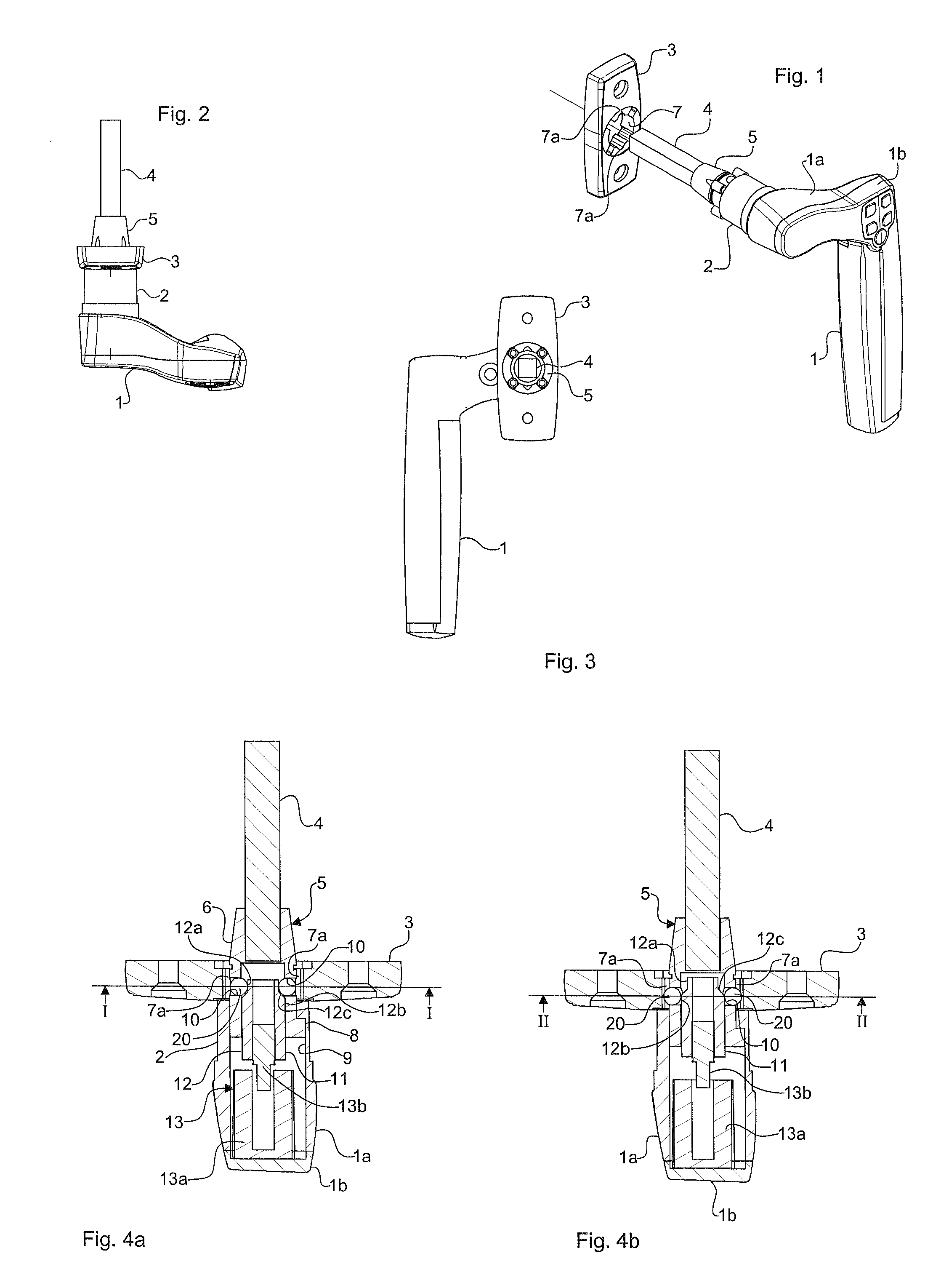
[0038]FIGS. 1, 2, 3, 4a, 4b, 8a and 8b show a handle device according to a first embodiment of the invention. This handle device is designed to allow selective disengagement and coupling between the handle grip and a fixed part. In the disengaged position, rotation of the handle grip is therefore allowed and in the coupled position the handle grip is prevented from being turned.

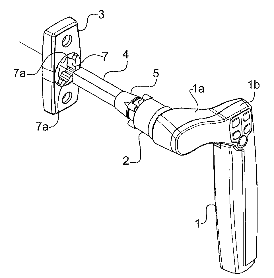
[0039]The handle device comprises a handle grip 1, a handle neck 2, a handle escutcheon 3 or plate and a swivel pin or handle spindle 4 in the form of a square shank.

[0040]The handle escutcheon 3 comprises fixing holes for receiving screws or the like, by means of which it can be fixed to a door, a window, a gate, a hatch (not shown) or a similar element. The handle escutcheon 3 further comprises a central through-hole 7, the central axis of which defines an axis of rotation for the handle grip. Two opposing grooves 7a are made in the central hole 7 of the handle escutcheon 3. The grooves 7a are formed as axi...


PUM


Abstract

Handle device for operating doors, windows and the like, comprising a first element, which is rotatable about an axis of rotation, a second element, and a coupling device which is connected to the first and the second element and is designed to selectively allow or prevent relative rotation about the axis of rotation between the first and the second element, the coupling device comprising an outer coupling member (3, 50) and an inner coupling member (5, 31), which is concentrically accommodated, rotatable about the axis of rotation, in the outer coupling member. The handle device comprises at least one engaging member (20), which is radially displaceable in the inner coupling member (5, 31), and an activating member (12, 60) which is accommodated in the inner coupling member and axially displaceable therein, parallel to the axis of rotation. The engaging member and the activating member have interacting contact surfaces (12b, 12c, 61, 63) in order, during axial displacement of the activating member, to press the engaging member into a radially projecting position for simultaneous engagement with the inner and outer coupling member.

Description

FIELD OF THE INVENTION[0001]The invention relates in general to a handle device for operating doors, windows, gates, hatches and the like. The invention relates in particular to such a handle device comprising a first element which is rotatable about an axis of rotation, a second element, and a coupling device for selectively allowing or preventing relative rotation about the axis of rotation between the first and the second element.BACKGROUND OF THE INVENTION[0002]In the case of many doors, windows and other such elements provided with a rotatable handle, it is desirable to be able to selectively couple a part that can be turned or rotated by means of the handle to another part, or to disengage it therefrom. The other part may consist either of a similarly rotatable part or of a fixed part.[0003]Where both of the parts are rotatable, it may be desirable in a disengaged state, for example, to allow the handle to be turned without affecting the other part and in a coupled state to al...

Claims


Application Information

Patent Timeline
Patent Type & Authority Applications(United States)
IPC IPC(8): E05B47/00E05B1/00
CPCE05B47/0004E05B47/0011E05B47/0673Y10T16/458E05B2047/0058E05B2047/0079E05B47/0692Y10T70/5416Y10T70/5796Y10T70/5823Y10T70/7062Y10T292/57E05B13/002E05B13/005E05B47/00
Inventor CALLEBERG, JOHAN
Owner ASSA OEM AB
Why Eureka
Try Eureka