Removable panels for a welding-type machine enclosure

a welding-type machine and enclosure technology, applied in the field of welding-type machines, can solve the problems of limited placement of welding-type machines, large space between welding-type machines and adjacent objects or building walls, and the side panels of hinged side panels required a great deal of space between welding-type machines and any adjacent objects or building walls, and achieve the effect of convenient removal

Active Publication Date: 2008-08-12
ILLINOIS TOOL WORKS INC
View PDF8 Cites 22 Cited by
  • Summary
  • Abstract
  • Description
  • Claims
  • Application Information

AI Technical Summary

Benefits of technology

[0005]The present invention solves the aforementioned problems by providing side panels that are installed on, and easily removable from, the welding-type machine within a min...

Problems solved by technology

However, the hinged side panels required a great deal of space between the welding-type machine and any adjacent objects or building walls.
Cons...

Method used


Image

  • Removable panels for a welding-type machine enclosure
  • Removable panels for a welding-type machine enclosure
  • Removable panels for a welding-type machine enclosure

Examples


Embodiment Construction

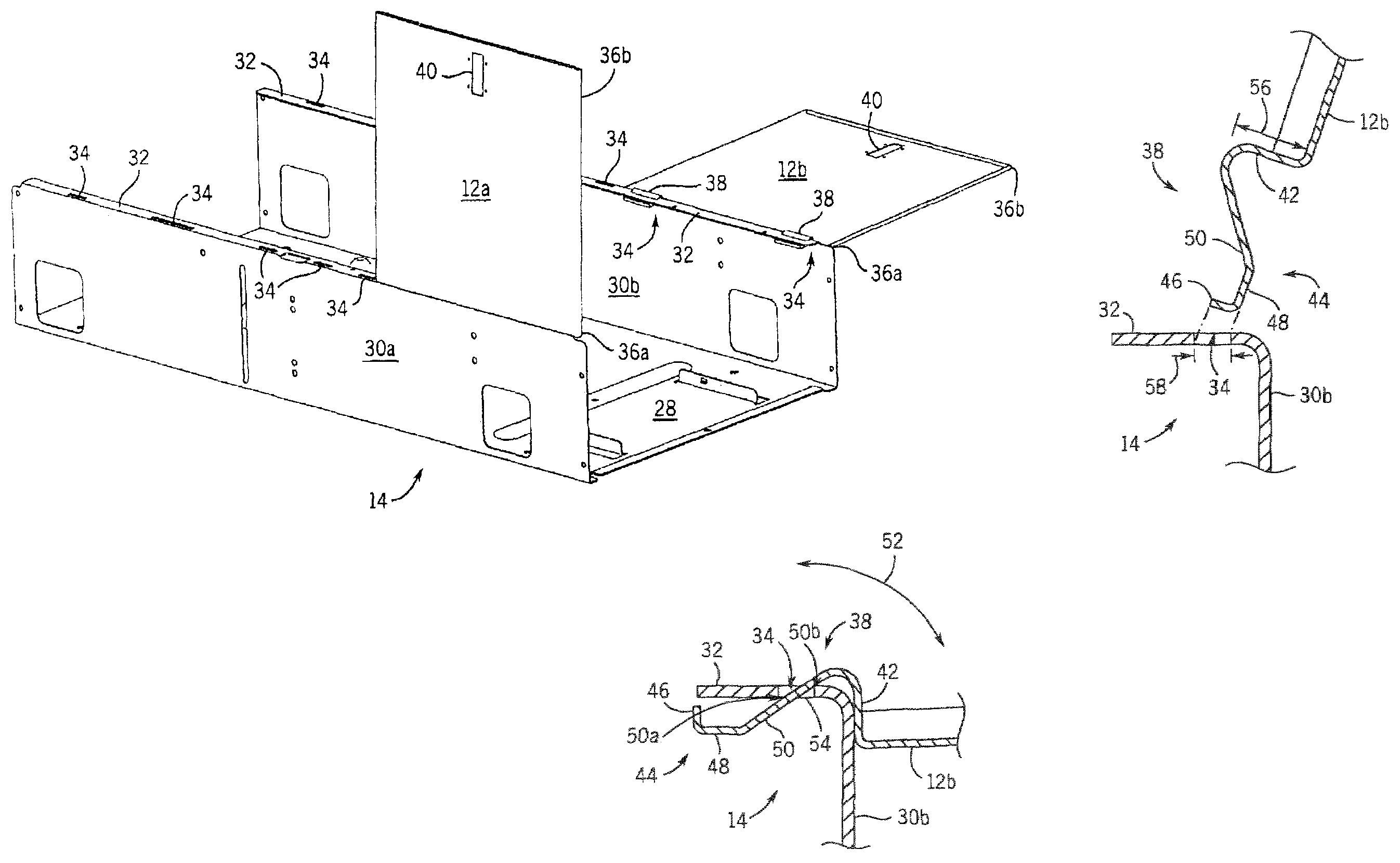
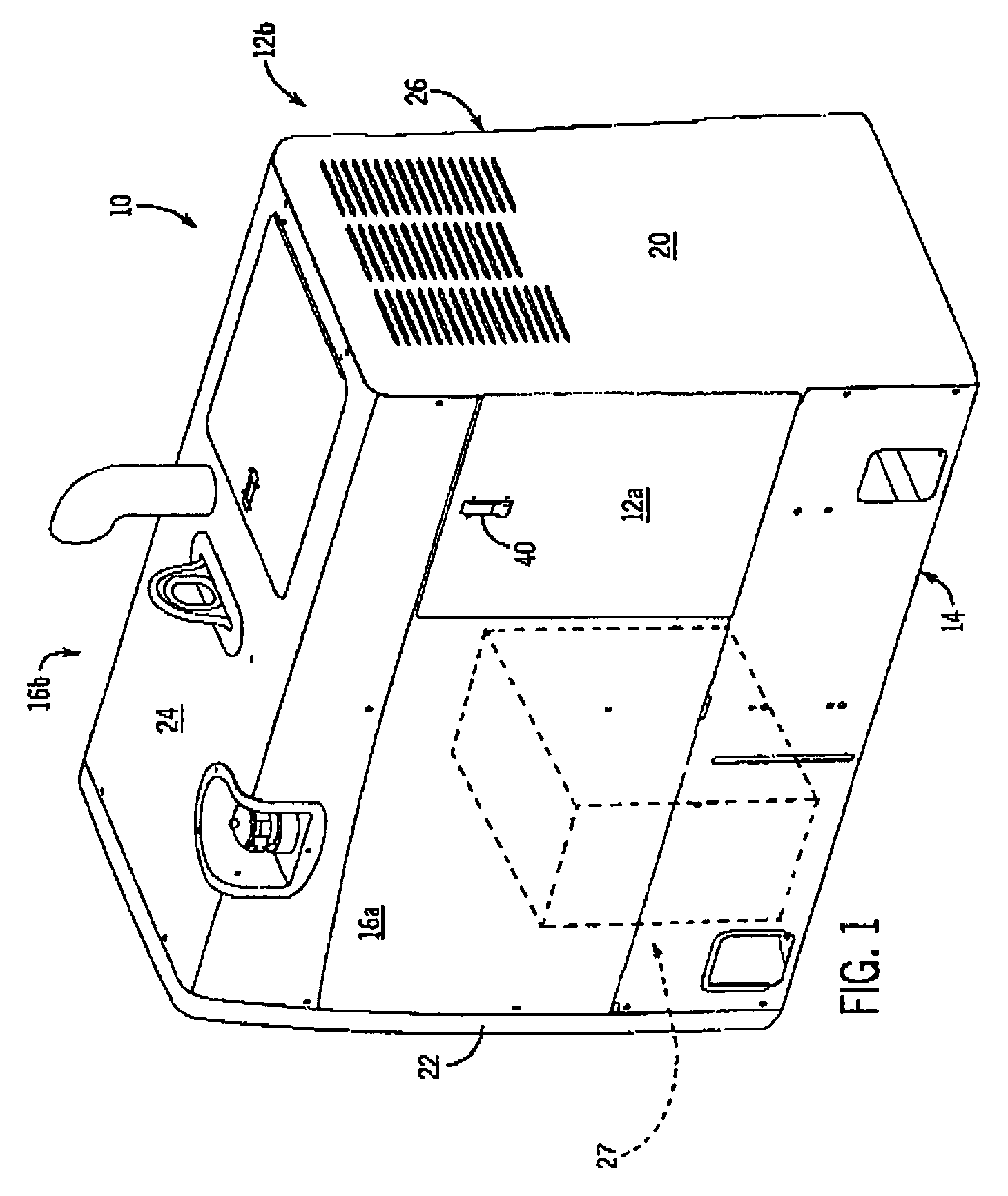
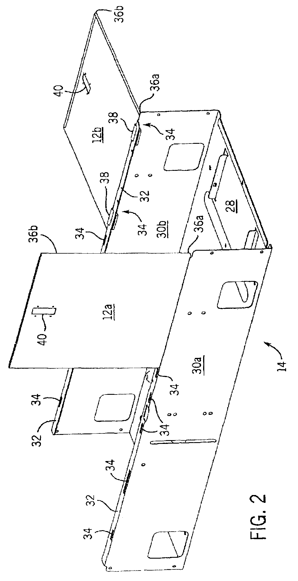
[0017]FIG. 1 is a perspective view of a welding-type machine 10, incorporating a pair of removable panels, where one removable panel 12a is shown in a closed position and another removable panel 12b (not shown) is on an opposite side of the welding-type machine 10. The welding-type machine 10 is merely representative of a wide variety of welding type machines having various sizes, features, and ratings.

[0018]The welding-type machine 10 includes a base 14, four side panels, two of which are removable side panels 12a and 12b, and two of which are fixed side panels 16a and 16b (not shown), welding-type machine, back panel 20, and a front panel 22 (not shown), all attached to the base 14. A top cover 24 is secured to the plurality of side panels to form an enclosure 26. While all these components are shown and described as individual, distinct components, it is understood that these components, or any combination thereof may be constructed as a unitary system or unitary panels. For exam...


PUM

PropertyMeasurementUnit
Angleaaaaaaaaaa
Angleaaaaaaaaaa
Angleaaaaaaaaaa

Abstract

A hinge arrangement for a welder enclosure includes a door panel having at least one hinge at one end that is engagable in a slot of a base to allow the door panel to move between a maximum closed position to a maximum open position. The hinge and slot arrangement of the door panel and base allow the door panel to open and close through a rotation point from a maximum open position to a maximum closed position, and also allows complete removal of the door panel at certain positions between the maximum open position and the maximum closed position.

Description

BACKGROUND OF INVENTION[0001]The present invention relates generally to welding-type machines and, more particularly, to a welding-type machine enclosure that incorporates removable panels for easy access into the welding-type machine.[0002]A typical welding-type machine includes an electric generator, a prime mover for rotating the generator to produce electrical power, and various electrical components that convert the power from the generator into power suitable for welding. The generator, prime mover, and electrical components are usually assembled into an enclosure having a base, a top wall, two end walls, and two side walls. A horizontal center wall divides the enclosure into an engine compartment and an electrical compartment. The base, top wall, center wall, and end walls normally stay permanently in place after manufacture of the welding-type machine. On the other hand, to provide access to the engine and electrical compartments the enclosure side walls may be removable.[00...

Claims


Application Information

Patent Timeline
IPC IPC(8): B23K9/10A47B81/00E05D1/00E05D7/10
CPCB23K9/10Y10T16/53613Y10T16/542Y10T16/5362
Inventor RADTKE, DAVID E.
Owner ILLINOIS TOOL WORKS INC
Why Eureka
Try Eureka