Solar tracker

a solar tracker and solar energy technology, applied in the field of photovoltaic modules, can solve the problems of high energy consumption of circuit boards 32 and 32, and the difficulty and therefore the cost of providing photo detectors

Inactive Publication Date: 2010-11-04
INST NUCLEAR ENERGY RES ROCAEC
View PDF21 Cites 10 Cited by
  • Summary
  • Abstract
  • Description
  • Claims
  • Application Information

AI Technical Summary

Benefits of technology

[0013]To achieve the foregoing objective, the solar tracker includes a sunlit-detecting unit, a control unit, a first motor and a second motor. The sunlit-detecting unit detect...

Problems solved by technology

Secondly, it includes detectors for detecting the position of the brightest object.
Problems have however been encountered in the use of the conventional solar tracker.
Secondly, the circuit board 32 consumes much energy because it carr...

Method used


Image

  • Solar tracker
  • Solar tracker
  • Solar tracker

Examples


Embodiment Construction

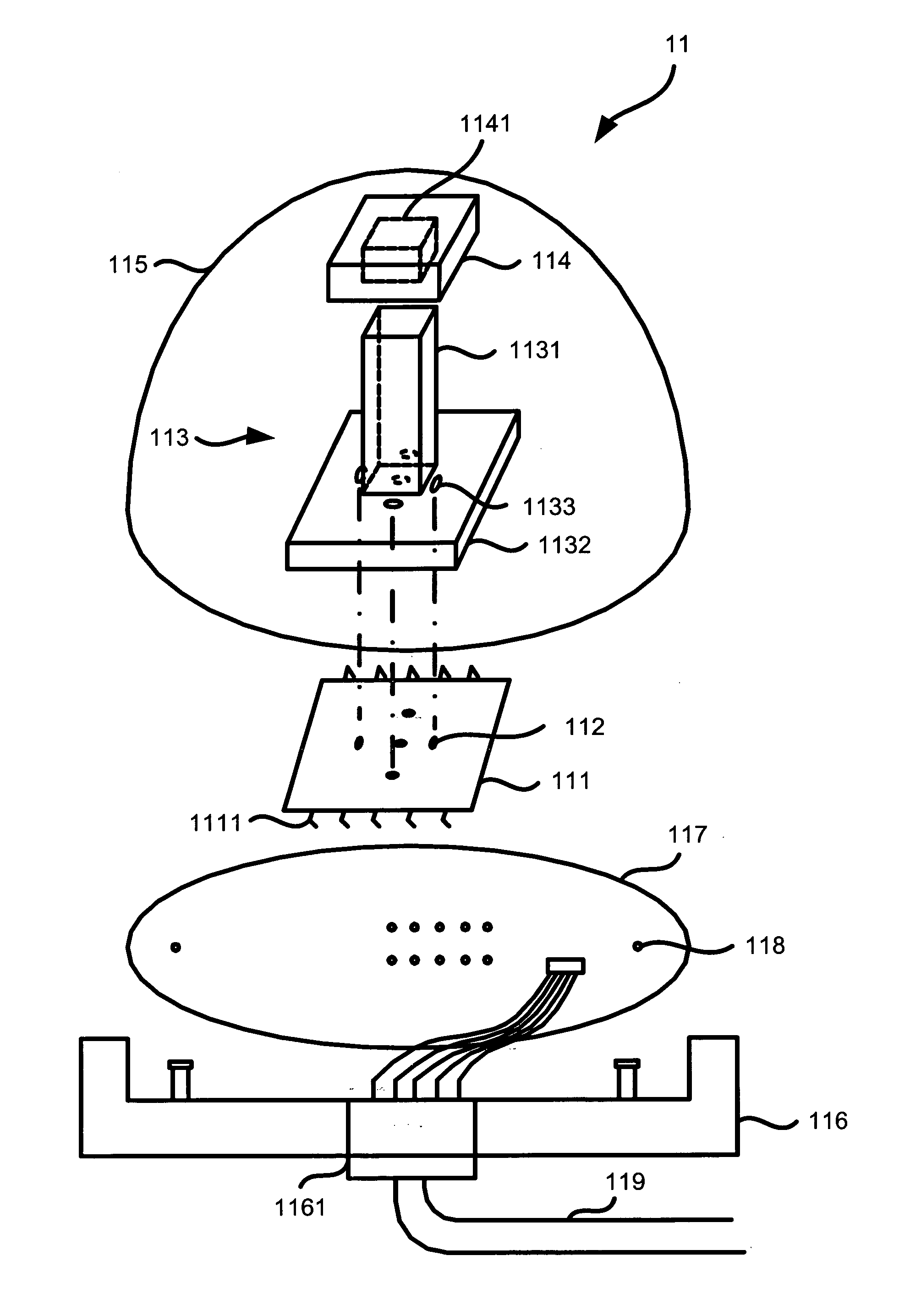
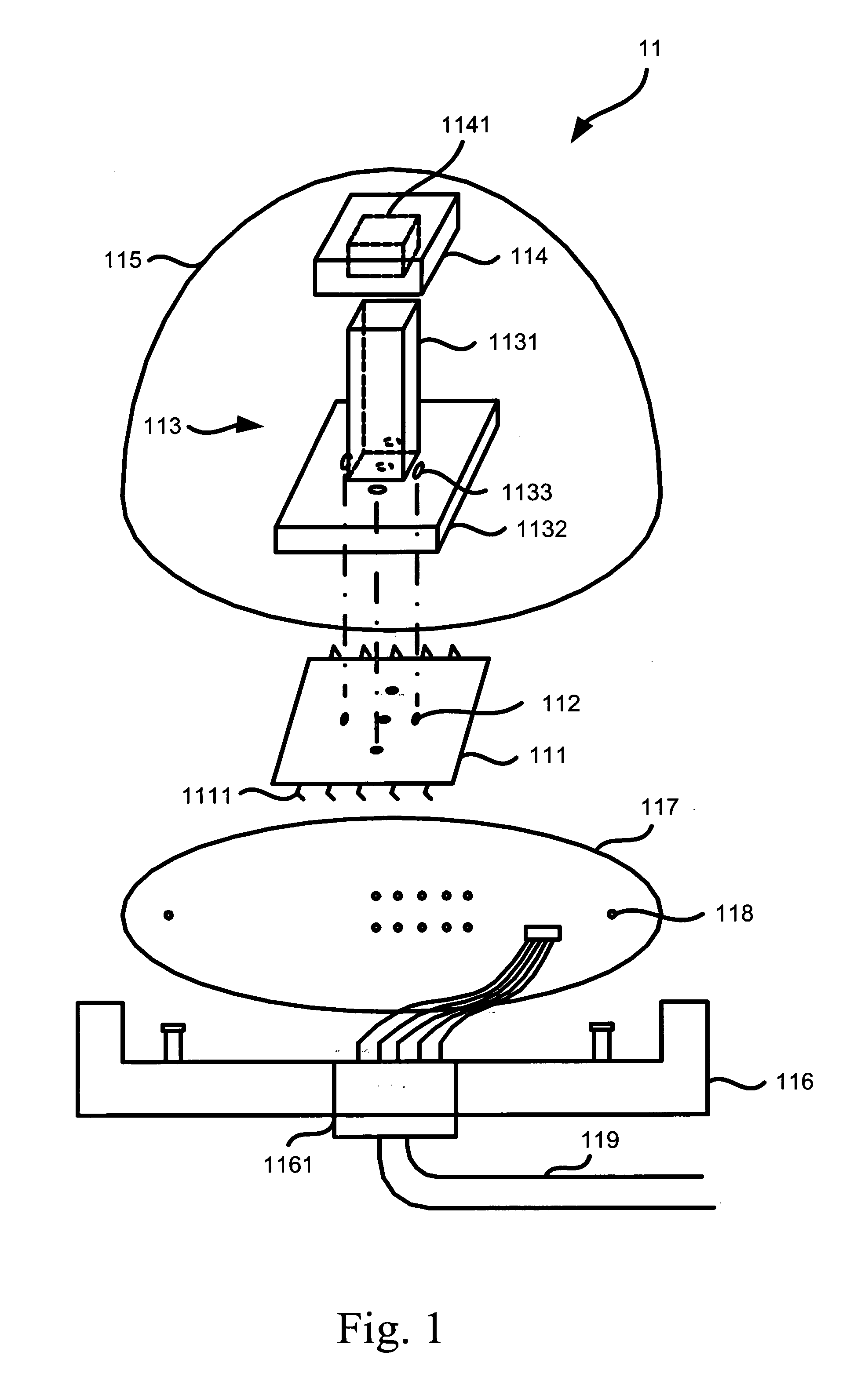
[0022]Referring to FIG. 3, a photovoltaic module includes a solar cell array 15 and a solar tracker 1 according to the preferred embodiment of the present invention. The solar cell array 15 is provided on a beam supported on a post. The beam can be rotated about the post, i.e., about a vertical axis. The term “rotation” will be used to represent the angular motion about the vertical axis. The beam can be tilted on the post, i.e., pivoted about a horizontal axis. The term “tilt” will be used to represent the angular motion about the horizontal axis. Thus, the solar cell array 15 always intercepts the sunlit perpendicularly.

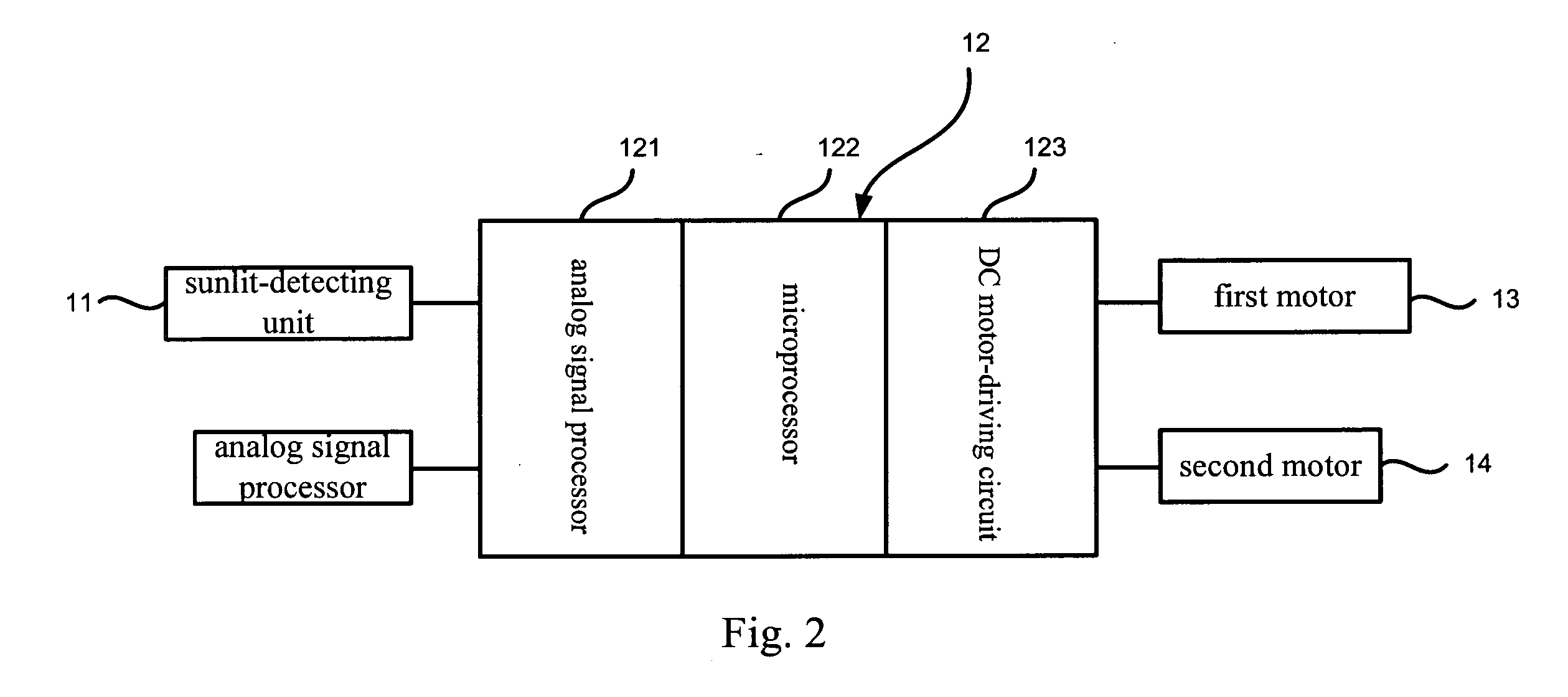
[0023]Referring to FIG. 2, the solar tracker 1 includes a sunlit-detecting unit 11, a control unit 12 connected to the sunlit-detecting unit 11, a first motor 13 connected to the control unit 12 and a second motor 14 connected to the control unit 12. The sunlit-detecting unit 11 detects the sunlit and sends signals to the control unit 12. Based on the signals, the ...


PUM


Abstract

A solar tracker includes a sunlit-detecting unit, a control unit, a first motor and a second motor. The sunlit-detecting unit detects the position of the sun. Based on the position of the sun, the control unit instructs the first motor to rotate a solar cell array and the second motor to tilt the solar cell array.

Description

BACKGROUND OF INVENTION[0001]1. Field of Invention[0002]The present invention relates to a photovoltaic module and, more particularly, to a solar tracker for a photovoltaic module.[0003]2. Related Prior Art[0004]A photovoltaic module includes a solar cell array mounted on a frame and a solar tracker for directing the solar cell array to the sun. Thus, the photoelectric efficiency of the solar cell array can be maximized.[0005]A typical solar tracker includes the follow properties. Firstly, it tracks the brightest object in the sky. Secondly, it includes detectors for detecting the position of the brightest object. Thirdly, its tolerance is 1 to 3 degrees. Fourthly, it includes an analog circuit.[0006]Referring to FIG. 5, as devised by Ronald P. Corio et al., a conventional solar tracker includes a shell 31, a circuit board 32 located in the shell 31 and four photo detectors 33 provided on the shell 31. The shell 31 includes four walls. Each of the photo detectors 33 is located on a ...

Claims


Application Information

Patent Timeline
IPC IPC(8): F24J2/38F24S50/20
CPCF24J2/38Y02E10/47F24J2/542F24J2/40H02S20/32F24S50/20F24S30/452F24S50/00Y02E10/50
Inventor YEH, HONG-YIHLEE, CHENG-DARCHYOU, SHANG-LEELIU, PAN-CHIH
Owner INST NUCLEAR ENERGY RES ROCAEC
Why Eureka
Try Eureka