Apparatus, System, and Method for Performing an Electrosurgical Procedure

a technology of electrosurgical procedure and apparatus, applied in the field of apparatus, system and method, can solve the problems of present design challenges and design challenges for a manufacturer of surgical instruments

Active Publication Date: 2010-11-11
TYCO HEALTHCARE GRP LP
View PDF76 Cites 103 Cited by
  • Summary
  • Abstract
  • Description
  • Claims
  • Application Information

AI Technical Summary

Benefits of technology

[0007]As noted above, smaller cannulas or access ports are usually preferred during an endoscopic procedure. However, because of size constraints associated with the cannula or access port, endoscopic forceps that are configured for use with the smaller cannulas may present design challenges for a manufacturer (e.g., designing an end effector assembly of an endoscopic forceps without compromising the integrity and / or functionality thereof).
[0008]Therefore, it may prove useful in the relevant arts to provide an endoscopic forceps that includes an end effector assembly that is configured for use with various types of cannulas or access ports including those that are less than five millimeters. With this purpose in mind, the present disclosure provides a bipolar forceps adapted to connect to a source of electrosurgical energy. The bipolar forceps includes a housing having a handle assembly including a movable handle and one or more shafts that extend from the housing that defines a longitudinal axis therethrough. An end effector assembly operatively connects to a distal end of the shaft and includes a pair of first and second jaw members movable from an open spaced apart position to a closed position to grasp tissue. A solenoid is in operative communication with the movable handle and operatively couples to a drive rod that operatively couples to at least one of the first and second jaw members for causing movement thereof. One or both of the first and second jaw members includes one or more teeth configured to engage one or more teeth located on the drive rod such that rotation of the solenoid imparts at least one of longitudinal and rotational movement of the drive rod such that at least one of the first and second jaw members moves from a first position to a second to clamp tissue.
[0009]The present disclosure also provides a method for performing an electrosurgical procedure. The method includes the initial step of providing a bipolar forceps adapted to connect to a source of electrosurgical energy. The bipolar forceps includes a housing having a handle assembly including a movable handle and one or more shafts that extend from the housing that defines a longitudinal axis therethrough. An end effector assembly operatively connects to a distal end of the shaft and includes a pair of first and second jaw members movable from an open spaced apart position to a closed position to grasp tissue. A solenoid is in operative communication with the movable handle and operatively couples to a drive rod that operatively couples to at least one of the first and second jaw members for causing movement thereof. One or both of the first and second jaw members includes one or more teeth configured to engage one or more teeth located on the drive rod such that rotation of the solenoid imparts at least one of longitudinal and rotational movement of the drive rod such that at least one of the first and second jaw members moves from a first position to a second to clamp tissue. The method also includes the steps of: positioning tissue between the pair of first and second jaw members; actuating the electromechanical device to move the drive rod causing the first and second jaw members to move towards each other such that tissue is grasped therebetween; and applying electrosurgical energy to the jaw members such that a tissue seal may be effected therebetween.
[0010]The present disclosure further provides a system for performing an electrosurgical device. The system includes a bipolar forceps adapted to connect to a source of electrosurgical energy. The bipolar forceps includes a housing having a handle assembly including a movable handle and one or more shafts that extend from the housing that defines a longitudinal axis therethrough. An end effector assembly operatively connects to a distal end of the shaft and includes a pair of first and second jaw members movable from an open spaced apart position to a closed position to grasp tissue. A solenoid is in operative communication with the movable handle and operatively couples to a drive rod that operatively couples to at least one of the first and second jaw members for causing movement thereof. One or both of the first and second jaw members includes one or more teeth configured to engage one or more teeth located on the drive rod such that rotation of the solenoid imparts at least one of longitudinal and rotational movement of the drive rod such that at least one of the first and second jaw members moves from a first position to a second to clamp tissue. The system also includes a control system having one or more algorithms for one of independently controlling and monitoring the delivery of electrosurgical energy from the source of electrosurgical energy to the electromechanical device and a tissue sealing plate on each of the jaw members.

Problems solved by technology

Forceps that are configured for use with small cannulas (e.g., cannulas less than five millimeters) may present design challenges for a manufacturer of surgical instruments.
However, because of size constraints associated with the cannula or access port, endoscopic forceps that are configured for use with the smaller cannulas may present design challenges for a manufacturer (e.g., designing an end effector assembly of an endoscopic forceps without compromising the integrity and / or functionality thereof).

Method used


Image

  • Apparatus, System, and Method for Performing an Electrosurgical Procedure
  • Apparatus, System, and Method for Performing an Electrosurgical Procedure
  • Apparatus, System, and Method for Performing an Electrosurgical Procedure

Examples


Embodiment Construction

[0020]Detailed embodiments of the present disclosure are disclosed herein; however, the disclosed embodiments are merely examples of the disclosure, which may be embodied in various forms. Therefore, specific structural and functional details disclosed herein are not to be interpreted as limiting, but merely as a basis for the claims and as a representative basis for teaching one skilled in the art to variously employ the present disclosure in virtually any appropriately detailed structure.

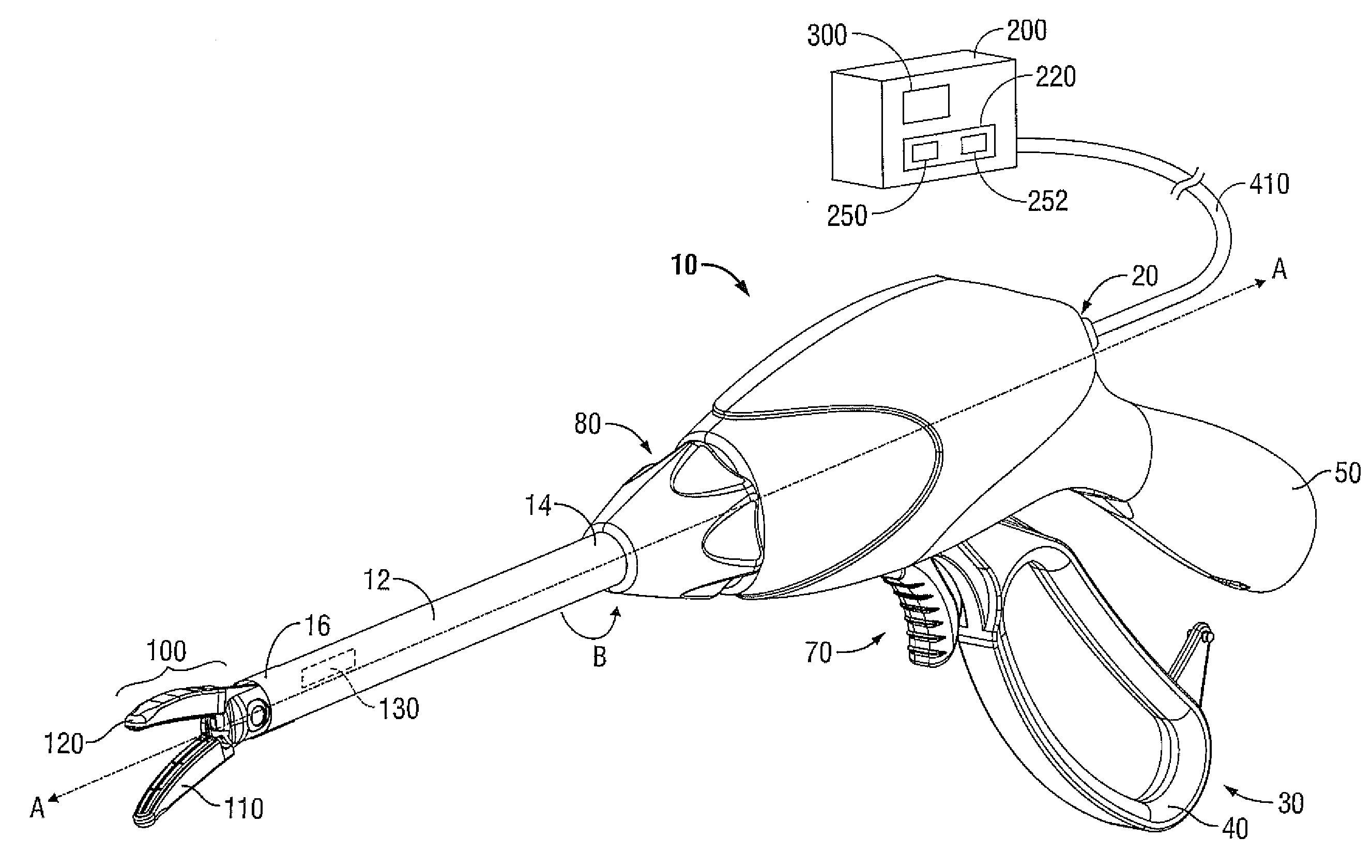
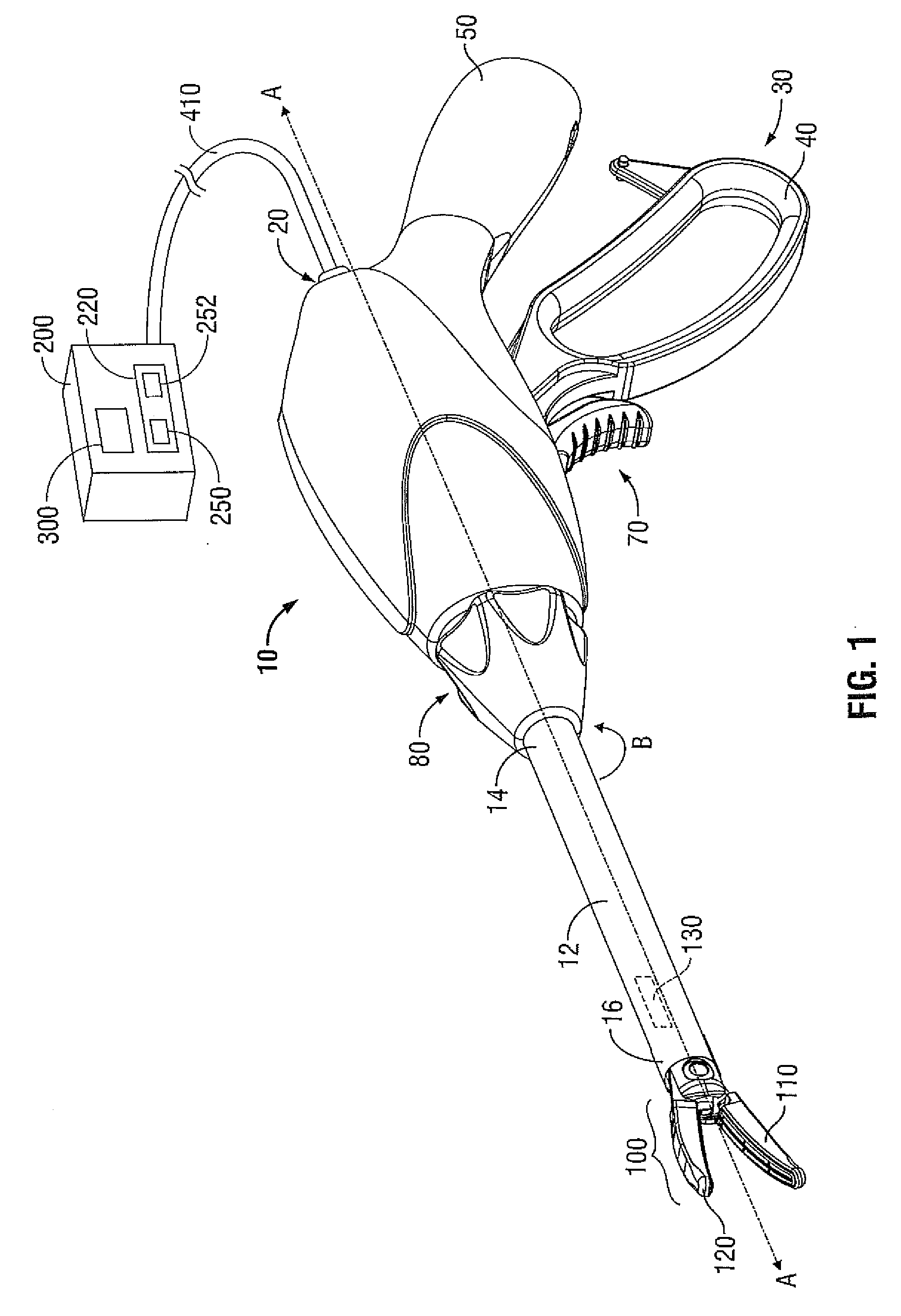
[0021]The present disclosure includes an electrosurgical apparatus (e.g., endoseopic or laparoseopic forceps) that includes an end effector assembly that includes a jaw assembly operatively coupled to one or more electromechanical drive assemblies for causing movement of the jaw assembly.

[0022]With reference to FIG. 1 an illustrative embodiment of an electrosurgical generator 200 (generator 200) is shown. Generator 200 operatively and selectively connects to an endoscopic or laparoscopic forceps (...


PUM


Abstract

The present disclosure provides a bipolar forceps. The bipolar forceps includes a housing having a handle assembly including a movable handle and one or more shafts. An end effector assembly operatively connects to a distal end of the shaft and includes a pair of first and second jaw members. A solenoid is in operative communication with the movable handle and operatively couples to a drive rod operatively coupled to at least one of the first and second jaw members for causing movement thereof. One or both of the first and second jaw members includes one or more teeth configured to engage one or more teeth located on the drive rod such that rotation of the solenoid imparts one of longitudinal and rotational movement of the drive rod such that at least one of the first and second jaw members moves between the open and closed positions.

Description

BACKGROUND[0001]1. Technical Field[0002]The present disclosure relates to an apparatus, system, and method for performing an electrosurgical procedure. More particularly, the present disclosure relates to an apparatus, system, and method for performing an electrosurgical procedure that employs an endoscopic or laparoscopic clectrosurgical apparatus that includes an end effector assembly configured for use with various size access ports.[0003]2. Description of Related Art[0004]Electrosurgical apparatuses (e.g., electrosurgical forceps) are well known in the medical arts and typically include a handle, a shaft and an end effector assembly operatively coupled to a distal end of the shaft that is configured to manipulate tissue (e.g., grasp and seal tissue). Electrosurgical forceps utilize both mechanical clamping action and electrical energy to effect hemostasis by heating the tissue and blood vessels to coagulate, cauterize, seal, cut, desiccate, and / or fulgurate tissue[0005]As an alt...

Claims


Application Information

Patent Timeline
Patent Type & Authority Applications(United States)
IPC IPC(8): A61B18/14
CPCA61B18/1206A61B2018/126A61B18/18A61B18/20A61B2017/2945A61B2018/00083A61B2018/00577A61B2018/00589A61B2018/00595A61B2018/00601A61B2018/0063A61B2018/00779A61B2018/00827A61B2018/00875A61B2018/00892A61B2018/1432A61B2018/0072A61B2018/00767A61B18/1445A61B2018/00702
Inventor KERR, DUANE E.GADSBY, PETER D.HORNER, GLENN A.
Owner TYCO HEALTHCARE GRP LP
Why Eureka
Try Eureka