Teleidoscopic display device

Inactive Publication Date: 2010-11-18
LONDON DAVID
View PDF14 Cites 14 Cited by
  • Summary
  • Abstract
  • Description
  • Claims
  • Application Information

AI Technical Summary

Benefits of technology

[0008]In one aspect of the invention, the present invention expands the traditional concept of kaleidoscopes and teleidoscopes by introducing new forms of teleidoscopes. In one aspect, the new forms which provide electronic image capture to the kaleidoscopic process may be body worn or supported. These images may then be subject to handling in ways which are beyond the abilities of traditional kaleidoscopes and teleidoscopes. For example, a kaleidoscopic image may be projected on a small screen carried on the user's body, may be projected on a larger screen where many viewers may view the images, transmitted remotely using communications channels, and digitally stored, to name some if not all of the possibilities. As employed herein, the term “kaleidoscopic image” will signify the visual end product both of kaleidoscopes and of teleidoscopes, since the optical effect arising from the two or more mirrors, three mirrors typically being used, are similar even if the source images are not.

Problems solved by technology

Usually, there is sufficient distortion from the actual viewable image such that a whimsical or abstract image results, with the actual viewed scene not being recognizable as such.

Method used


Image

  • Teleidoscopic display device
  • Teleidoscopic display device
  • Teleidoscopic display device

Examples


Embodiment Construction

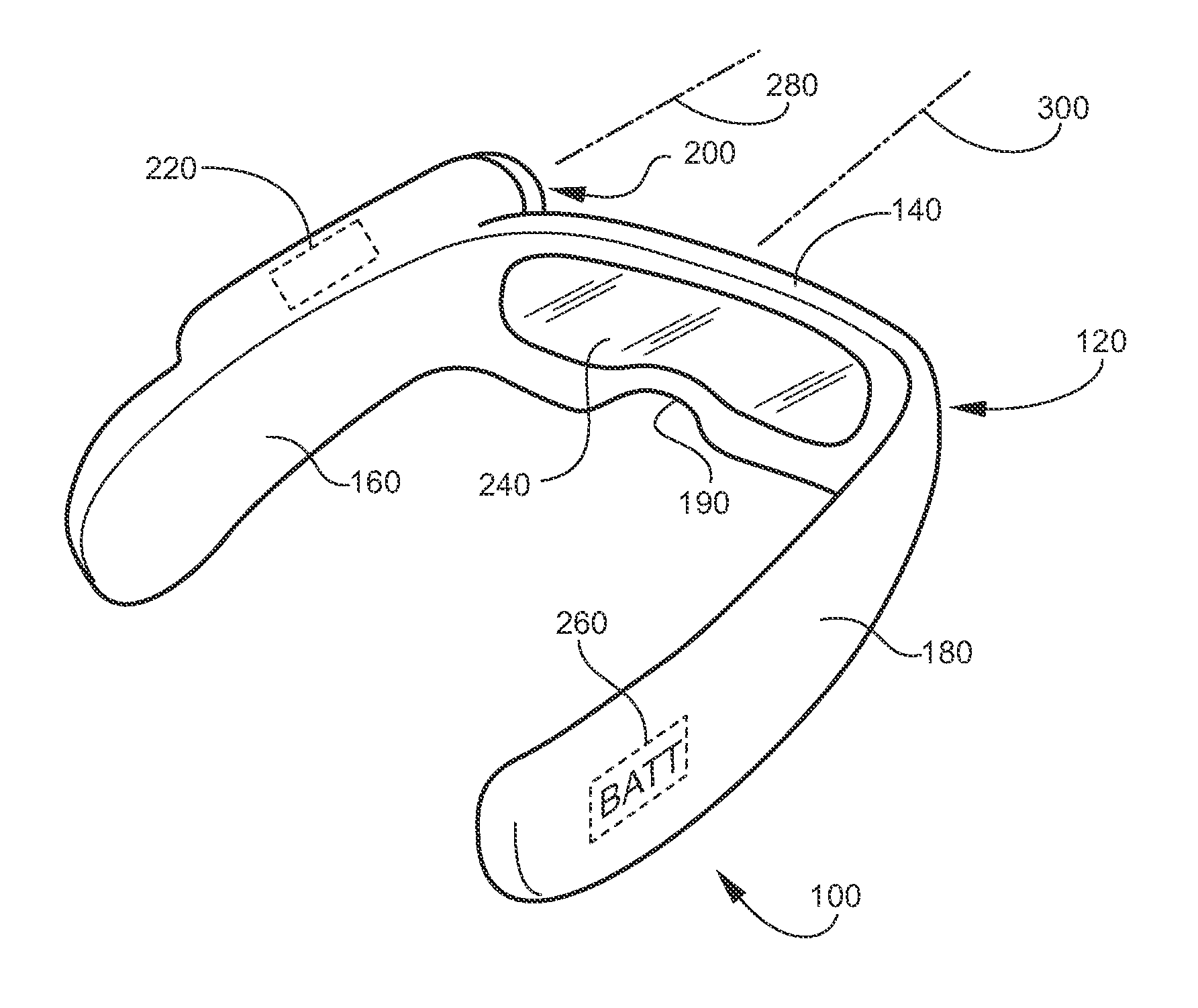
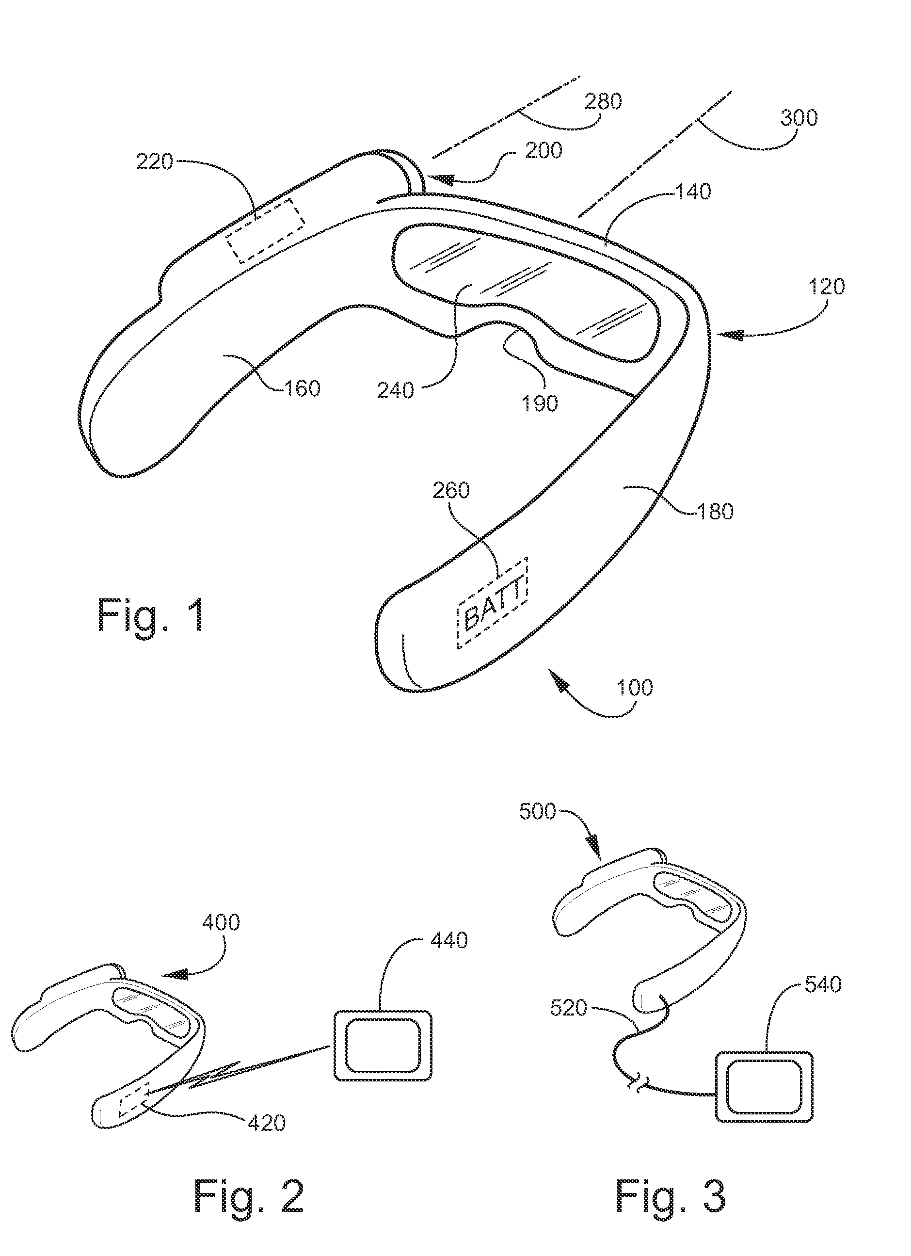
[0023]FIG. 1 shows a teleidoscopic device 100 for generating and displaying kaleidoscopic images according to at least one aspect of the invention. The terms “teleidoscope” and “teleidoscopic device” are hereinafter regarded as equivalent terms.

[0024]The teleidoscopic device 100 may comprise a mounting structure 120 for engaging the human body (not shown) and being supported thereon. More particularly, the mounting structure 120, which may be worn in a manner akin to that of eyeglasses, may comprise a front section 140 which spans the eyes of the wearer, a first ear piece 160, and a second ear piece 180. The ear pieces 160, 180 are disposed to engage a person's head and ears, and to be capable of being supported on the head such that the device 100 is wearable as are eyeglasses. The ear pieces 160, 180 may be integrally formed with the front section 140, as shown, or alternatively, may be hinged thereto or otherwise connected. The front section 140 may cooperate with the face of the...


PUM


Abstract

A body supported teleidoscopic device having an onboard electronic image capture device, such as a digital camera, and a display screen. The teleidoscopic device has an onboard battery and controlling circuitry. The teleidoscopic device may comprise a pistol grip handle for being hand held, or may comprise earpieces so as to be wearable in the manner of eyeglasses. The display screen may be onboard or remote. Where remote, the display screen may be provided with wireless or hard wired connection to the kaleidoscopic image source. The teleidoscopic device may comprise a projector for large scale display of images for group viewing. The teleidoscopic device may be focused on a screen to generate kaleidoscopic imagery using video feedback techniques. The projector and screen may take the form of a television.

Description

CROSS-REFERENCE TO RELATED APPLICATIONS[0001]This application claims the benefit of priority from U.S. Provisional Patent Application Ser. No. 61 / 178,952 (filed May 16, 2009). The entire content of Provisional Patent Application Ser. No. 61 / 178,952 is incorporated herein by reference in its entirety.STATEMENT REGARDING FEDERALLY SPONSORED RESEARCH OR DEVELOPMENT[0002]Not Applicable.FIELD OF THE INVENTION[0003]The present invention pertains to amusement devices of the type which display kaleidoscopic optical effects, and more particularly to a device which incorporates electronic capture and handling of kaleidoscopic optical effects.BACKGROUND OF THE INVENTION[0004]Kaleidoscopes have long been used as amusement devices. In a conventional kaleidoscope, the user holds a tube-shaped device up to their eye to view a complex pattern of changing colors and shapes. The tube-shaped device is rotated to produce a succession of symmetrical designs by means of mirrors reflecting the constantly ...

Claims


Application Information

Patent Timeline
Patent Type & Authority Applications(United States)
IPC IPC(8): G09G5/00
CPCG02B27/017G02B27/08G09G2380/02G02B2027/0178G02B2027/0138
Inventor LONDON, DAVID
Owner LONDON DAVID
Why Eureka
Try Eureka