Tool Assembly with Coaxial/Universal Coupling

a technology of universal coupling and tool assembly, which is applied in the direction of wrenches, screwdrivers, manufacturing tools, etc., can solve the problems of unreliable positioning effect and increase manufacturing costs

Inactive Publication Date: 2010-11-25
HU BOBBY
View PDF4 Cites 19 Cited by
  • Summary
  • Abstract
  • Description
  • Claims
  • Application Information

AI Technical Summary

Problems solved by technology

However, formation of the receptacle and recesses and mounting of the ball and the spring in the engaging member of the tool shank are time-consuming and increase the manufacturing costs.
The resulting positioning effect is unreliable.

Method used


Image

  • Tool Assembly with Coaxial/Universal Coupling
  • Tool Assembly with Coaxial/Universal Coupling
  • Tool Assembly with Coaxial/Universal Coupling

Examples


first embodiment

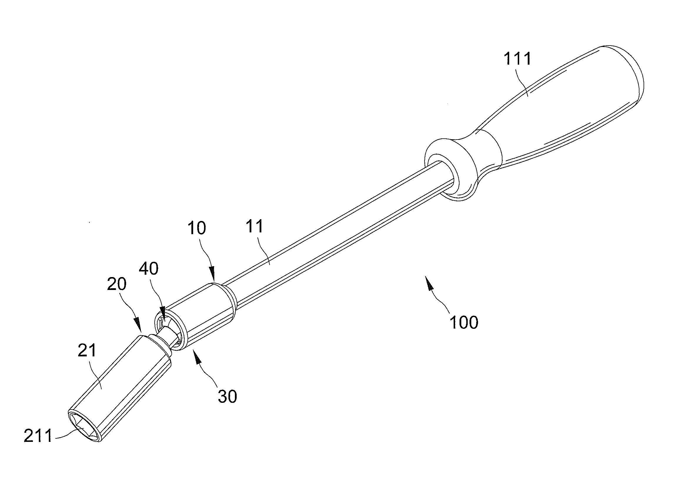
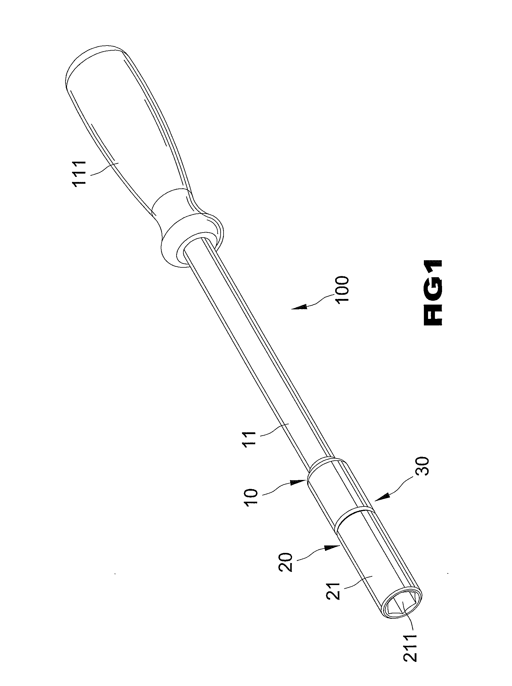
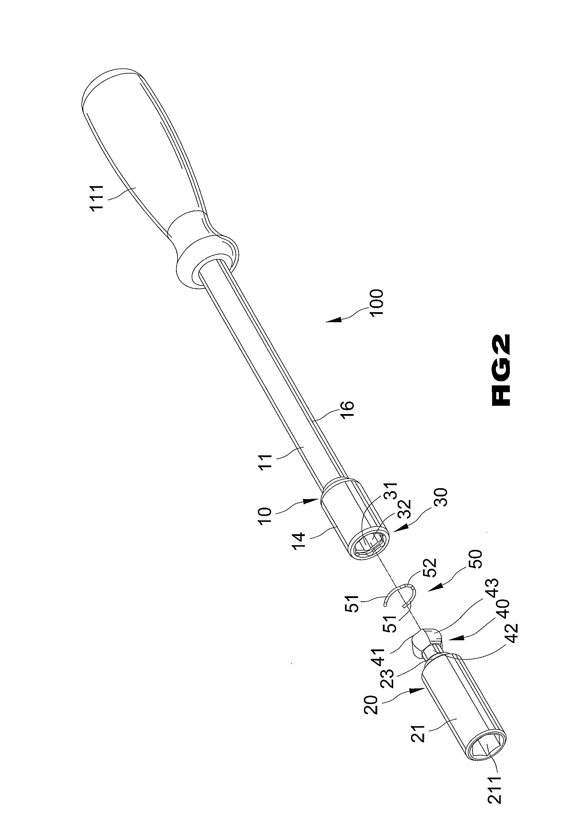
[0043]Now that the basic construction of tool assembly 100 of the first embodiment according to the preferred teachings of the present invention has been explained, the operation and some of the advantages of tool assembly 100 can be set forth and appreciated. In particular, for the sake of explanation, it will be assumed that head 41 is the first position (see FIGS. 1, 3, 4, 11, and 12). In this position, shoulder 23 is received in receptacle 31 of sleeve portion 30, and first C-clip 50 distends and clamps the outer periphery of shoulder 23 to keep the longitudinal axis of adapter 20, 20A to be coaxial to the longitudinal axis of body 10, 10A. This is because the inner diameter of first C-clip 50 in the undistended state is smaller than third diameter D3. Thus, adapter 20, 20A and body 10, 10A can be coaxial to each other during joint rotation thereof. Note that the outer diameter of first C-clip 50 clamped around the outer periphery of shoulder 23 is within the extent of first ret...

second embodiment

[0045]Operation and some of the advantages of tool assembly 100 of the second embodiment according to the preferred teachings of the present invention will now be set forth. In particular, for the sake of explanation, it will be assumed that head 41 is the first position (FIGS. 15-17 and 23). In this position, shoulder 23 is received in receptacle 31 of sleeve portion 30, and first C-clip 50 clamps the outer periphery of shoulder 23 to keep the longitudinal axis of adapter 20, 20A to be coaxial to the longitudinal axis of body 10, 10A. Note that the outer diameter of first C-clip 50 clamped around the outer periphery of shoulder 23 is not larger than the diameter of first retaining groove 33. Furthermore, second C-clip 60 clamps the outer periphery of head 41 between first and second diameter D1 and D2. It can be appreciated that first and second C-clips 50 and 60 securely clamp and, thus, retain adapter 20, 20A in coaxial relationship with body 10, 20A. Thus, adapter 20, 20A and bo...


PUM


Abstract

A tool assembly includes a body having a receptacle. An adapter includes a shoulder, a head, and a neck interconnecting the head and the shoulder. The head engages with an inner periphery of the receptacle, allowing joint rotation of the adapter and the body. The head is slideably received in the receptacle between first and second positions. A C-clip is received in a retaining groove in the inner periphery of the receptacle. When the head is in the first position, the shoulder is received in the receptacle, the C-clip distends and clamps the shoulder to keep the adapter to be coaxial to the body. When the head is in the second position, the shoulder is outside of the receptacle, the C-clip abuts an outer periphery of the head, and the head is rotatable to a position such that the adapter is at an angle to the body.

Description

BACKGROUND OF THE INVENTION[0001]The present invention relates to a tool assembly with coaxial / universal coupling and, more particularly, to a tool assembly selectively providing coaxial or universal coupling by utilizing one or two C-clips.[0002]A type of tool assembly allowing coaxial / universal coupling includes a tool mount having a hole in an end thereof. A tool shank includes an end having a rounded engaging member received in the hole. A C-clip is mounted in the hole to retain the engaging member in the hole. The other end of the tool mount can receive a bit or engage with a driving device. The other end of the tool shank can engage with a driving device or a socket. The hole of the tool mount includes a plurality of flat surfaces each having a recess. The engaging member includes a receptacle receiving a ball and a spring biasing the ball to engage with one of the recesses, positioning the engaging member in the hole while the tool mount is coaxial to the tool shank. The tool...

Claims


Application Information

Patent Timeline
Patent Type & Authority Applications(United States)
IPC IPC(8): B25B23/16B25B23/00
CPCB25B13/481B25G1/063B25B23/12B25B23/0028
Inventor HU, BOBBY
Owner HU BOBBY
Why Eureka
Try Eureka