Micro-adjustable parallel bench vise

Inactive Publication Date: 2010-11-25
HUNG YI PO
View PDF10 Cites 14 Cited by
  • Summary
  • Abstract
  • Description
  • Claims
  • Application Information

AI Technical Summary

Benefits of technology

[0006]The present invention has been accomplished in view of these circumstances. It is one object of the present invention to provide a micro-adjustable parallel bench vise, which allows micro-adjustment of the position of multiple vises on one slide holder subject to the design of a dovetail rail on the slide holder and a dovetail groove

Problems solved by technology

However, in actual practice, it is difficult to have the pitch of the teeth 101 and the pitch of the teeth 201 get the same precision.
However, due to the limitation of

Method used


Image

  • Micro-adjustable parallel bench vise
  • Micro-adjustable parallel bench vise
  • Micro-adjustable parallel bench vise

Examples


Example

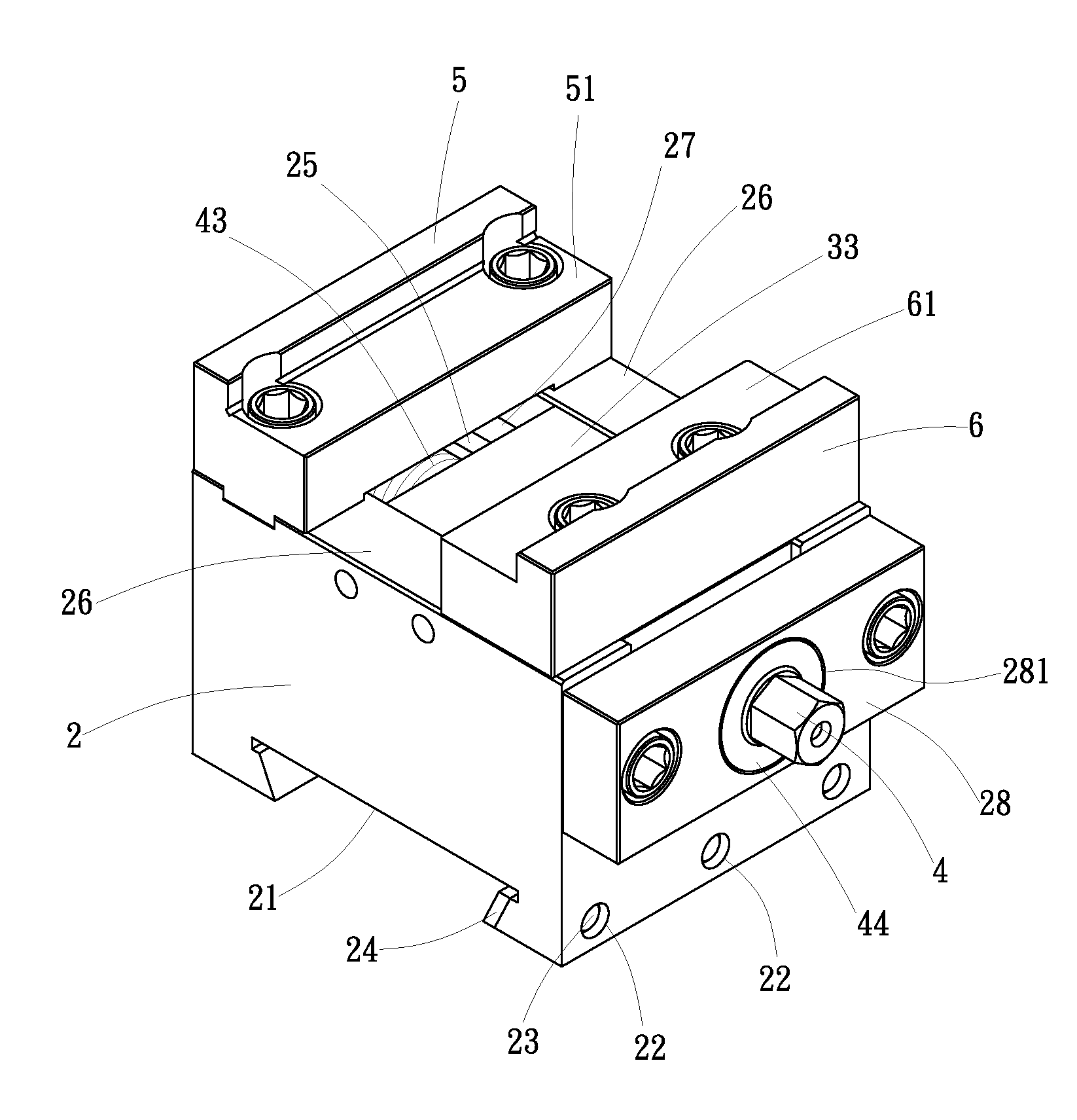
[0023]Referring to the annexed drawings in detail, a micro-adjustable parallel bench vise in accordance with the present invention is shown comprising a slide holder 1, a vise body 2, a screw holder 3, a screw rod 4, a fixed jaw member 5 and a movable jaw member 6.

[0024]The slide holder 1, as shown in FIGS. 4 and 5, is an elongated rectangular block having a dovetail rail 11 located on the top side thereof and two coupling grooves 12 arranged at two opposite lateral sides thereof in parallel. Two angled pressure blocks 13 are respectively coupled to the coupling grooves 12 and affixed to a worktable or other equipment to hold the slide holder 1 in place.

[0025]The vise body 2, as shown in FIGS. 4˜9, has a dovetail groove 21 located on the bottom side thereof and coupled to the dovetail rail 11 of the slide holder 1. The extending direction of the dovetail groove 21 and the extending direction of the screw rod 4 can be arranged at right angles. Alternatively, the extending direction o...


PUM


Abstract

A micro-adjustable parallel bench vise includes a slide holder having a top dovetail rail, a vise body having a bottom dovetail groove coupled to the dovetail rail of the slide holder and holding a fixed jaw member, a screw holder slidably mounted in the top side of the vise body, a screw rod threaded into the screw holder and rotatable to move the screw holder relative to the vise body. When multiple vise bodies are mounted on the slide holder in parallel, they are micro-adjustable to hold a workpiece or multiple workpieces precisely in position.

Description

BACKGROUND OF THE INVENTION[0001](a) Field of the Invention[0002]The present invention relates to a bench vise and more particularly to a micro-adjustable parallel bench vise, which allows micro-adjustment of the positions of multiple vises on one slide holder.[0003](b) Description of the Prior Art[0004]A conventional parallel bench vise, as shown in FIGS. 1 and 2, includes a rack 10 having a series of teeth 101, a fixed jaw member 20 having a series of teeth 201 on its top side, a slope 202 on its one end and a clamping face 203 on its opposite end, a movable jaw member 30 having a slope 301 on its one end and a clamping face 302 on its opposite end, and a wedge block 40 set in between the slope 202 of the fixed jaw member 20 and the slope 301 of the movable jaw member 30. When forcing the wedge block 40 downwards, the movable jaw member 30 is moved along the rack 10 to clamp a workpiece 50.[0005]According to the aforesaid prior art design, the teeth 101 of the rack 10 are meshed w...

Claims


Application Information

Patent Timeline
IPC IPC(8): B25B1/10B25B1/24
CPCB25B1/2484B25B1/103
Inventor HUNG, YI-PO
Owner HUNG YI PO
Why Eureka
Try Eureka