Method for joining components

Inactive Publication Date: 2009-05-07
MTU AERO ENGINES GMBH
View PDF14 Cites 24 Cited by
  • Summary
  • Abstract
  • Description
  • Claims
  • Application Information

AI Technical Summary

Benefits of technology

[0007]In the inventive method for joining components, the two components that are to be joined together are not moved with friction directly against one another but instead a joining part is inserted between them to serve as an intermediate part. The two components to be joined together are stationary and the joining part is moved in relation to the two components to be joined together. A compressive force is applied to the joint faces between the components that are to be joined together and the joining part and it is applied via the two stationary components. With the help of the inventive method, the two substeps of “rubbing” and “compressing” can be separated and iso

Problems solved by technology

If the two components that are to be joined together are brought together directly with friction, complex clamping devices are required, especially on the moving components.
This may result in deformation of the components to be joined together.
In addition, the frictional movement of the components to be joined together re

Method used


Image

  • Method for joining components
  • Method for joining components

Examples


Example

DETAILED DESCRIPTION OF THE DRAWINGS

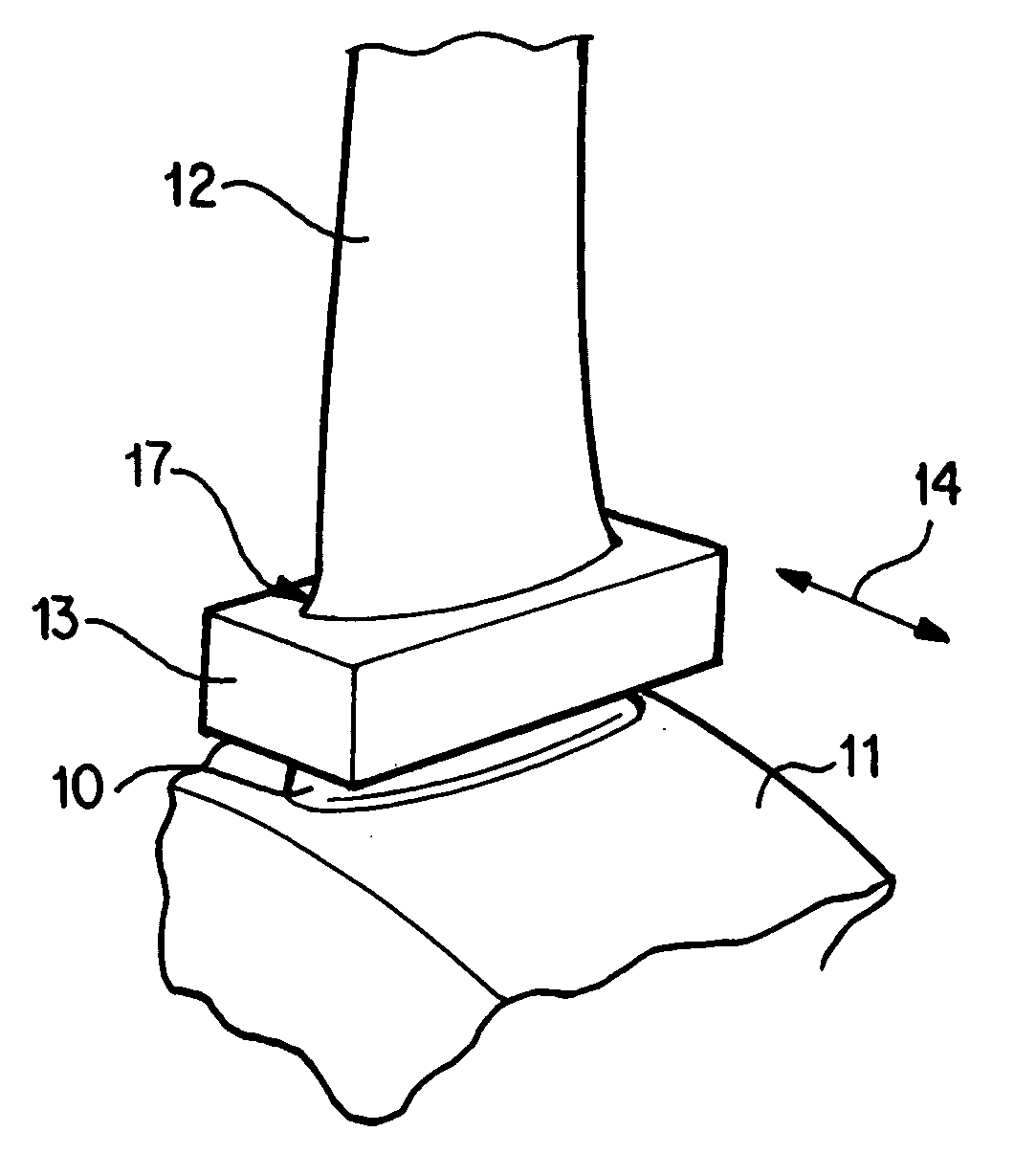
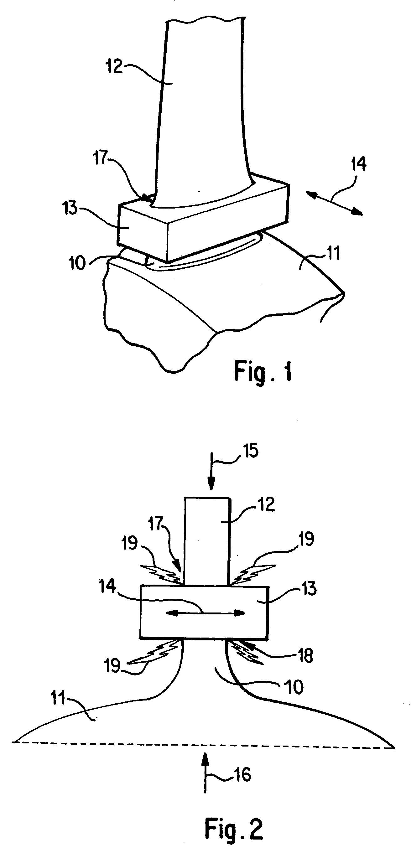
[0013]The present invention is described in greater detail below with reference to FIGS. 1 and 2.

[0014]FIGS. 1 and 2 illustrate the inventive method for joining components in the manufacture and / or repair of an integrally bladed gas turbine, whereby a blade pan 12 is to be joined to a protuberance on a rotor base body 11.

[0015]In the sense of the present invention, in addition to the two components to be joined together, namely in addition to the rotor base body 11 and the blade pan 12, a joining part 13 is also provided. For joining the blade pan 12 to the protuberance 10 on the rotor base body 11, the blade pan 12, the rotor base body 11 and the joining part 13 are aligned with one another so that the joining part 13 is arranged, i.e., positioned, between the protuberance 10 and the blade pan 12.

[0016]For joining the blade pan 12 and the rotor base body 11, the joining part 13 is moved back and forth in a translational and / or linear movement in ...


PUM

PropertyMeasurementUnit
Lengthaaaaaaaaaa
Lengthaaaaaaaaaa
Lengthaaaaaaaaaa

Abstract

A method for joining components, in particular for joining a rotor blade to a rotor base body in the manufacture and/or repair of an integrally bladed gas turbine rotor, is disclosed. The method includes the following steps: a) providing two components that are to be connected, i.e., joined together; b) providing a joining part; c) aligning the two components and the joining part that are to be joined together such that the joining part is arranged as an insert between the two components that are to be joined together; d) connecting the two components with the intermediate arrangement of the joining part by moving the joining part with respect to the two stationary components that are to be joined together and in particular by exerting a compression force on the joining zones between the two stationary components and the joining part via the two stationary components.

Description

[0001]This application claims the priority of German Patent Document No. 10 2005 009 769.3, filed Mar. 3, 2005, the disclosure of which is expressly incorporated by reference herein.BACKGROUND AND SUMMARY OF THE INVENTION[0002]The present invention relates to a method for joining components, in particular for joining a rotor blade to a rotor base body in the manufacture or repair of an integrally bladed gas turbine rotor.[0003]In fabrication of gas turbines, friction welding is a widely used joining method. Friction welding is a so-called solid state welding process. In friction welding, a distinction is made between so-called linear friction welding, so-called rotary friction welding and so-called friction stir welding. In friction welding, components are joined by friction. In linear friction welding, a component is moved back and forth with a translational movement, while the other component remains stationary and is pressed with a certain force against the moving component. In d...

Claims


Application Information

Patent Timeline
IPC IPC(8): B23P15/04
CPCB23K20/1205Y10T29/49321B23K20/16B23K20/233B23K2201/001B23K2203/14B23P6/005B23P15/006F01D5/005F01D5/30F01D5/3061F01D5/34F05B2230/239F05D2230/60F05D2230/80B23K20/129B23K2101/001B23K2103/14
Inventor BAMBERG, JOACHIMSATZGER, WILHELM
Owner MTU AERO ENGINES GMBH
Why Eureka
Try Eureka