Method and device for monitoring a drive unit, especially of a window lifter, comprising a rotating drive motor

A technology for driving equipment and equipment, which is applied in emergency protection circuit devices, power control mechanisms, power supplies, etc., and can solve problems such as small clamping forces

Inactive Publication Date: 2014-05-07
BROSE FAHRZEUGTEILE GMBH & CO KG HALLSTADT
View PDF7 Cites 22 Cited by
  • Summary
  • Abstract
  • Description
  • Claims
  • Application Information

AI Technical Summary

Problems solved by technology

But what is expected

Method used


Image

  • Method and device for monitoring a drive unit, especially of a window lifter, comprising a rotating drive motor
  • Method and device for monitoring a drive unit, especially of a window lifter, comprising a rotating drive motor
  • Method and device for monitoring a drive unit, especially of a window lifter, comprising a rotating drive motor

Examples


Embodiment Construction

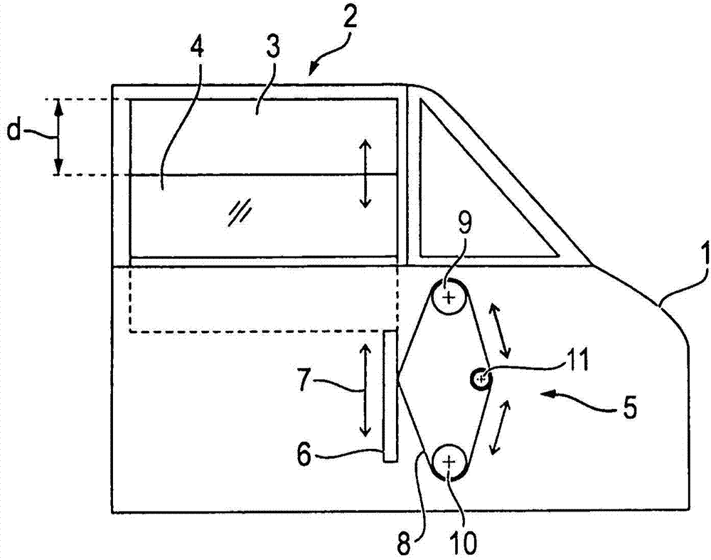
[0054] figure 1 Shown is a motor vehicle door 1 comprising a window 2 with a window 3 and a pane 4 . When the window 2 is closed, the width d of the window 3 is reduced to zero when the window pane 4 is moved into the upper guide (upper section) of the window 3 and locked.

[0055] also, figure 1 Also shown schematically is a window lifter 5 with a driver 6 which is connected to the window pane 4 and is guided in a guide not shown in further detail. The driver 6 can be moved in two directions indicated by the double arrow 7 , namely upwards in the closing direction and downwards in the opening direction. The driver 6 is connected to a drive cable 8 which is guided between two deflection or guide rollers 9 , 10 via a cable drum 11 . The cable drum 11 is drivable, so that the driver 6 and thus the window 4 can be adjusted in the opening and closing direction by means of the cable 8 .

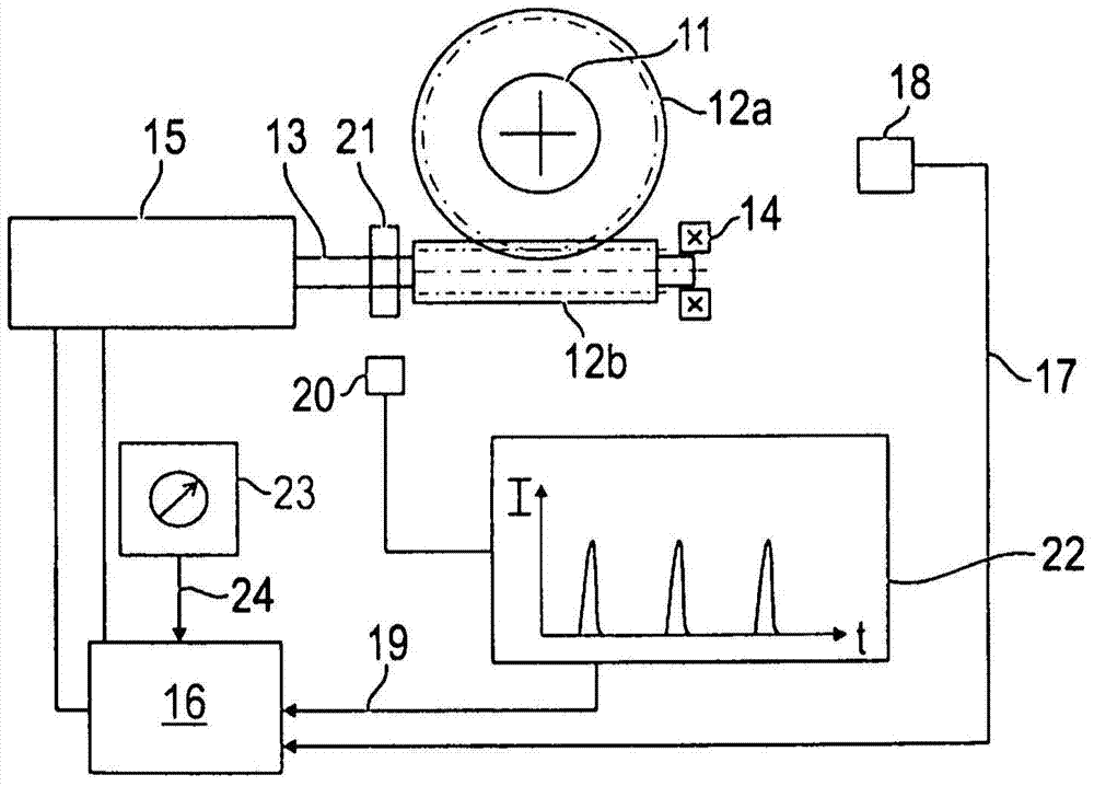
[0056] figure 2 Shown is the rope drum 11 or its associated worm gear 12 a , which meshe...


PUM


Abstract

The aim of the invention is to devise an improved anti-trap protection unit for an electric window lifter (5) of a vehicle or generally to efficiently limit excess forces of an adjusting element (4) that can be driven by means of a drive unit (A). For this purpose, a compensation trajectory of the drive unit (A) is determined independent of the temperature, and a variable threshold function (33, 34) which is dependent on the temperature is determined as a function of the drive trajectory or the drive time, the threshold function (33, 34) approaching a defined threshold value asymptotically, and the drive force especially in the form of a measured speed of a drive motor (15) being continuously determined and being monitored in accordance with the determined threshold function (33, 34).

Description

technical field [0001] The field of the invention relates to the fields of mechanical engineering and electronics, and can be used particularly advantageously in motor vehicle technology and is directed specifically at a method for monitoring an electric drive device for a drivable adjustment element, in particular a window pane or a sliding sunroof, and Device wherein the force of the actuatable element is monitored for anti-pinch protection. Background technique [0002] In electric window regulators of motor vehicles, for example, such an anti-trap protection is provided, which ensures that when closing the window, the reaction force to be overcome by the drive is monitored within the framework of the automatic closing device and is implemented in the following manner Limitation, that is, only the maximum allowable force (typically 100N) can be applied to the clamped object, otherwise the drive stops and / or reverses automatically. [0003] Electric window lifts, which ar...

Claims


Application Information

Patent Timeline
IPC IPC(8): H02H7/085E05F15/00
CPCH02H7/0851H02H7/0858E05Y2900/55E05Y2400/58E05Y2900/50E05F15/41E05F15/75E05F15/40
Inventor 马库斯·施勒西格罗兰德·卡尔巴
Owner BROSE FAHRZEUGTEILE GMBH & CO KG HALLSTADT
Why Eureka
Try Eureka