Head suspension
- Summary
- Abstract
- Description
- Claims
- Application Information
AI Technical Summary
Benefits of technology
Problems solved by technology
Method used
Image
Examples
first embodiment
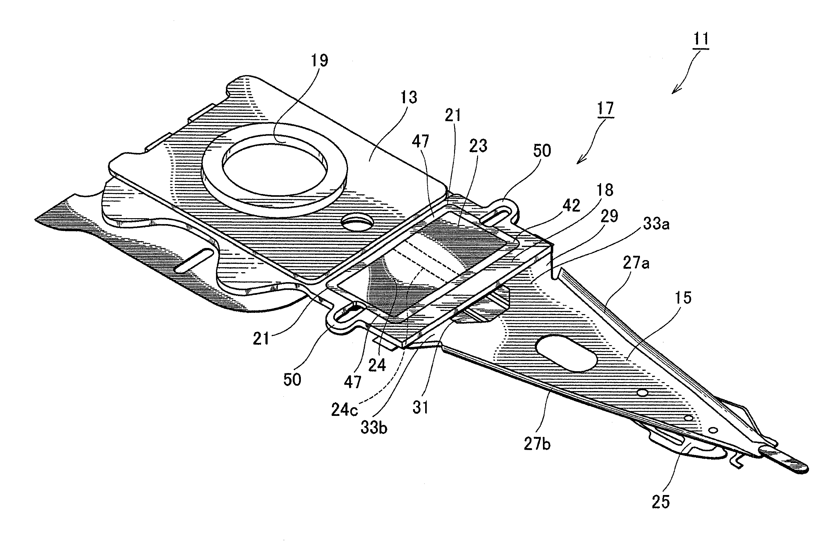
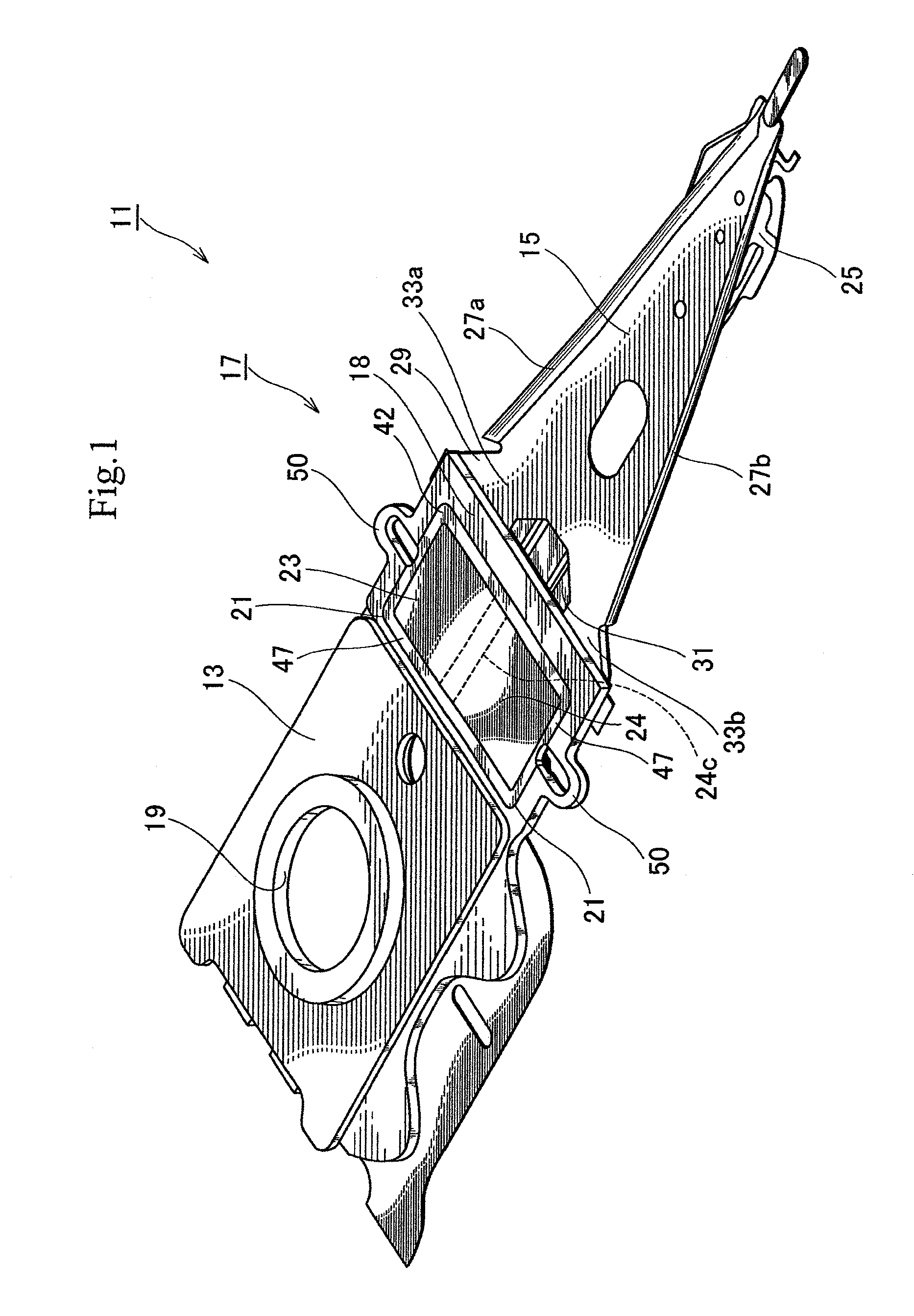
[0028]FIG. 1 is a perspective view illustrating a head suspension 11 according to the present invention. As shown in FIG. 1, the head suspension 11 has a base plate 13, a load beam 15, and a piezoelectric actuator 17.
[0029]The base plate 13 is a metal thin plate made of, for example, stainless steel and has a thickness of about 150 to 200 μm. The base plate 13 may be made of light metal such as aluminum alloy or a clad material including light metal and stainless steel. The light metal may reduce the inertia of the base plate 13, increase the resonant frequency of the head suspension 11 in a sway direction, i.e., a widthwise direction of the head suspension 11, and improve the tracing performance of the head suspension 11.
[0030]The base plate 13 has a circular boss 19. With the boss 19, the base plate 13 is attached to a front end of an actuator arm (not illustrated) and is turned by a voice coil motor (not illustrated). The base plate 13 has a front end proximate to the load beam 1...
second embodiment
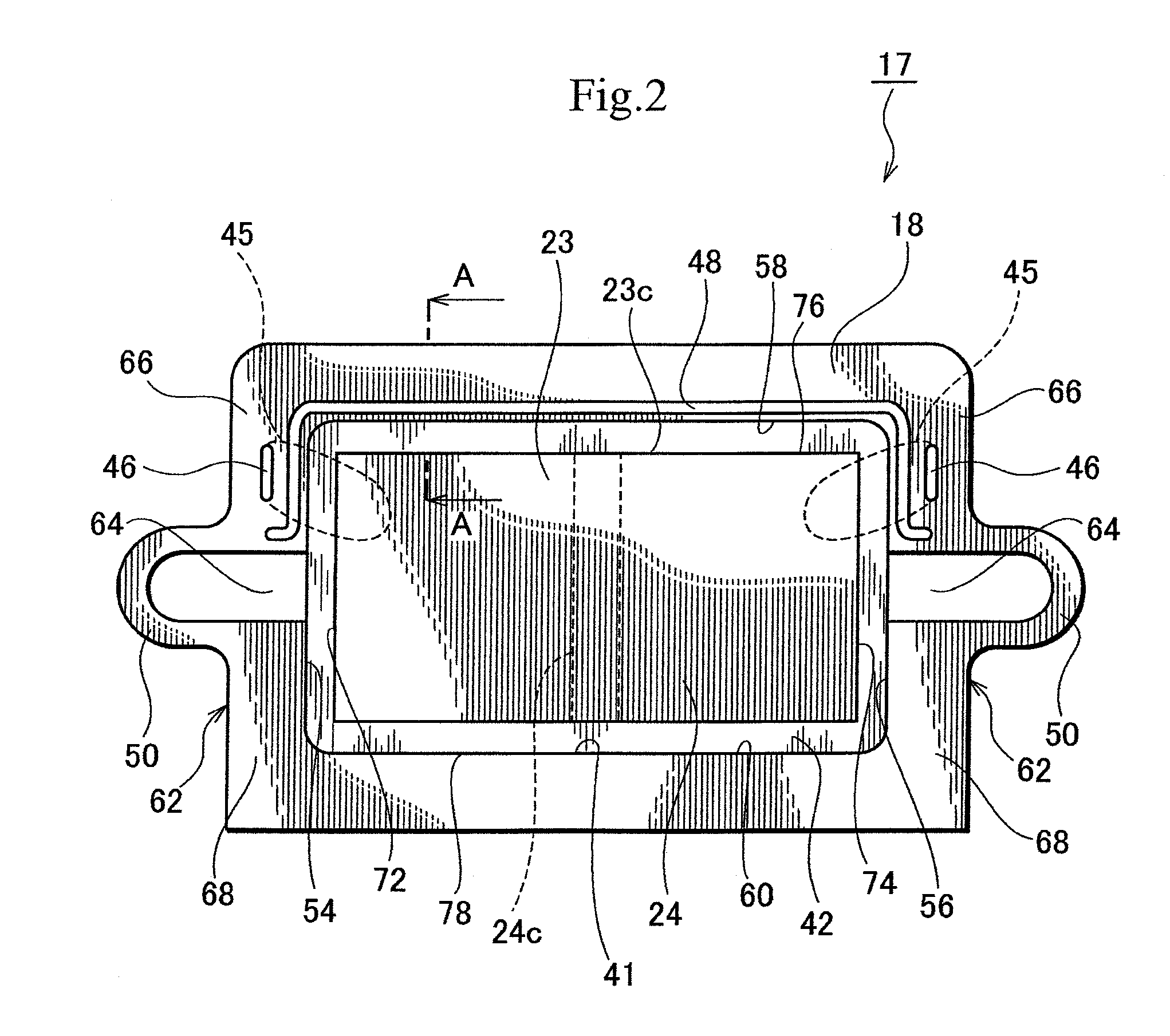
[0087]More precisely, the trap 63 is linearly formed along a front edge 58 of a circumferential edge 41 of the opening 21 in an area on a load beam 15 side of the actuator base 18. The trap 63 extends in a sway direction. There is no trap 63 along left and right edges 54 and 56 of the opening 21. That is, there is no trap 63 between the piezoelectric element 23 and conductive parts 46.
[0088]The second embodiment provides the same effect as the first embodiment. In addition, the second embodiment smoothly secures electrical connection between the piezoelectric element 23 and the conductive parts 46 without interference of the trap 63.
[0089]According to the first embodiment (FIG. 2), the trap 48 is present between the piezoelectric element 23 and the conductive parts 46, and the conductive paste 45 may flow along the trap 48.
[0090]On the other hand, the second embodiment prevents the conductive paste 45 from flowing along the trap 63.
[0091]The second embodiment is modifiable as illus...
third embodiment
[0096]The trap 73 is separated from the trap 63 by a discontinuous part 75 that is a part of an actuator base 18 of the piezoelectric actuator 71. Namely, the discontinuous part 75 separates the traps 63 and 73 from each other. At least one trap (73) is arranged between the piezoelectric element 23 and the conductive part 46. It is possible to arrange a plurality of traps between the piezoelectric element 23 and the conductive part 46. the trap 73 is longer than the conductive part 46 and is shorter than the trap 63.
[0097]The third embodiment provides the same effect as the second embodiment. In addition, the third embodiment arranges the discrete trap 73 between the piezoelectric element 23 and the conductive part 46, to improve the effect of preventing a conductive adhesive 47 from diffusing.
[0098]Since the trap 73 is separate from the trap 63, it functions to prevent a conductive paste 45 from flowing into the trap 63.
[0099]The third embodiment is modifiable as illustrated in FI...
PUM
| Property | Measurement | Unit |
|---|---|---|
| thickness | aaaaa | aaaaa |
| thickness | aaaaa | aaaaa |
| thickness | aaaaa | aaaaa |
Abstract
Description
Claims
Application Information
 - R&D
- Intellectual Property
- Life Sciences
- Materials
- Tech Scout
- Unparalleled Data Quality
- Higher Quality Content
- 60% Fewer Hallucinations
Browse by: Latest US Patents, China's latest patents, Technical Efficacy Thesaurus, Application Domain, Technology Topic, Popular Technical Reports.
© 2025 PatSnap. All rights reserved.Legal|Privacy policy|Modern Slavery Act Transparency Statement|Sitemap|About US| Contact US: help@patsnap.com


