Head suspension

Active Publication Date: 2012-03-27
NHK SPRING CO LTD
View PDF8 Cites 49 Cited by
  • Summary
  • Abstract
  • Description
  • Claims
  • Application Information

AI Technical Summary

Benefits of technology

[0013]An object of the present invention is to provide a head suspension capable of preventing the periphery of an opening of the head suspension to which a piezoelectric element is attached with a nonconductive adhesive from being spoiled with the nonconductive adhesive.
[0015]According to this aspect of the present invention, the trap holds the nonconductive adhesive if it overflows to the periphery of the opening, thereby preventing the nonconductive adhesive from diffusing and spoiling the periphery of the opening.

Problems solved by technology

An important issue for the head suspension employing the dual actuator system is to protect the brittle piezoelectric elements from damage and secure electric insulation between the head suspension body and the piezoelectric elements.
The related art, however, has a possibility of, when attaching the piezoelectric element to the opening, oozing the nonconductive adhesive out of the periphery of the opening and spoiling the vicinities of the opening.

Method used


Image

  • Head suspension
  • Head suspension
  • Head suspension

Examples


first embodiment

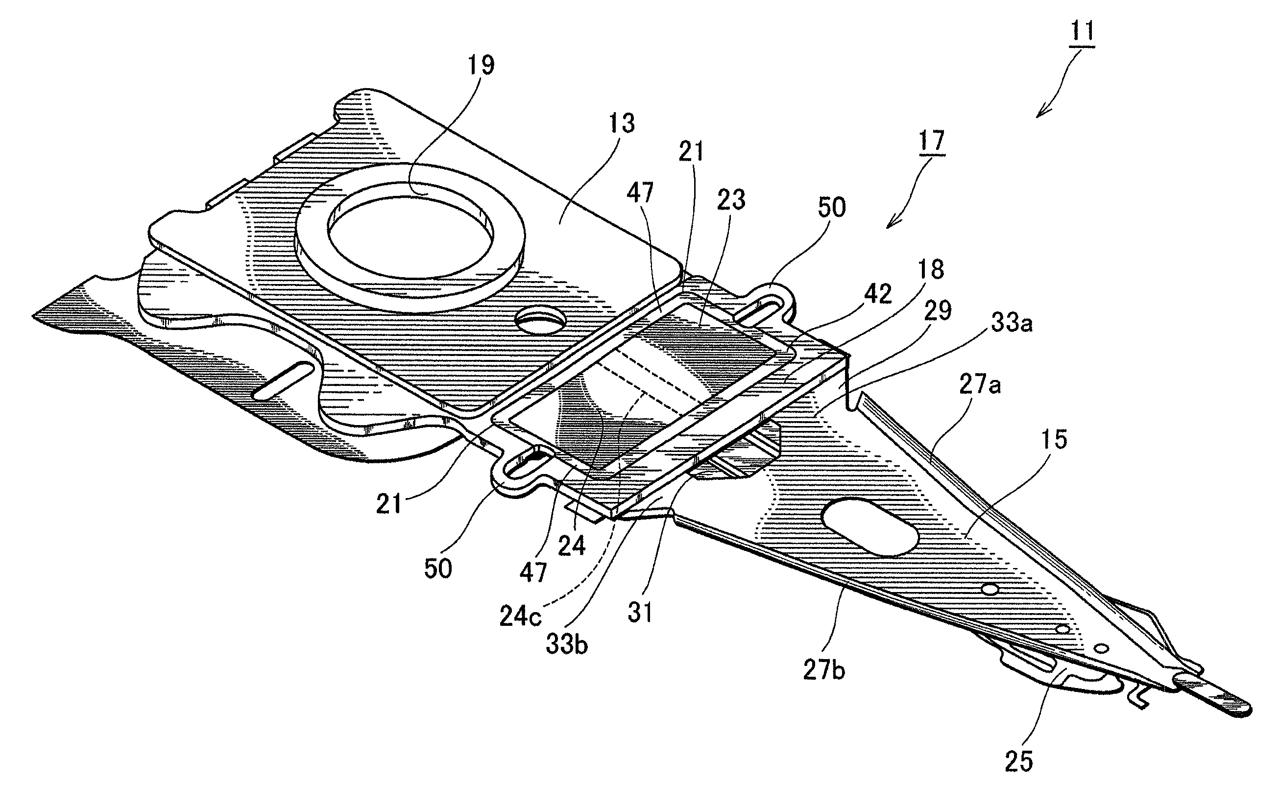
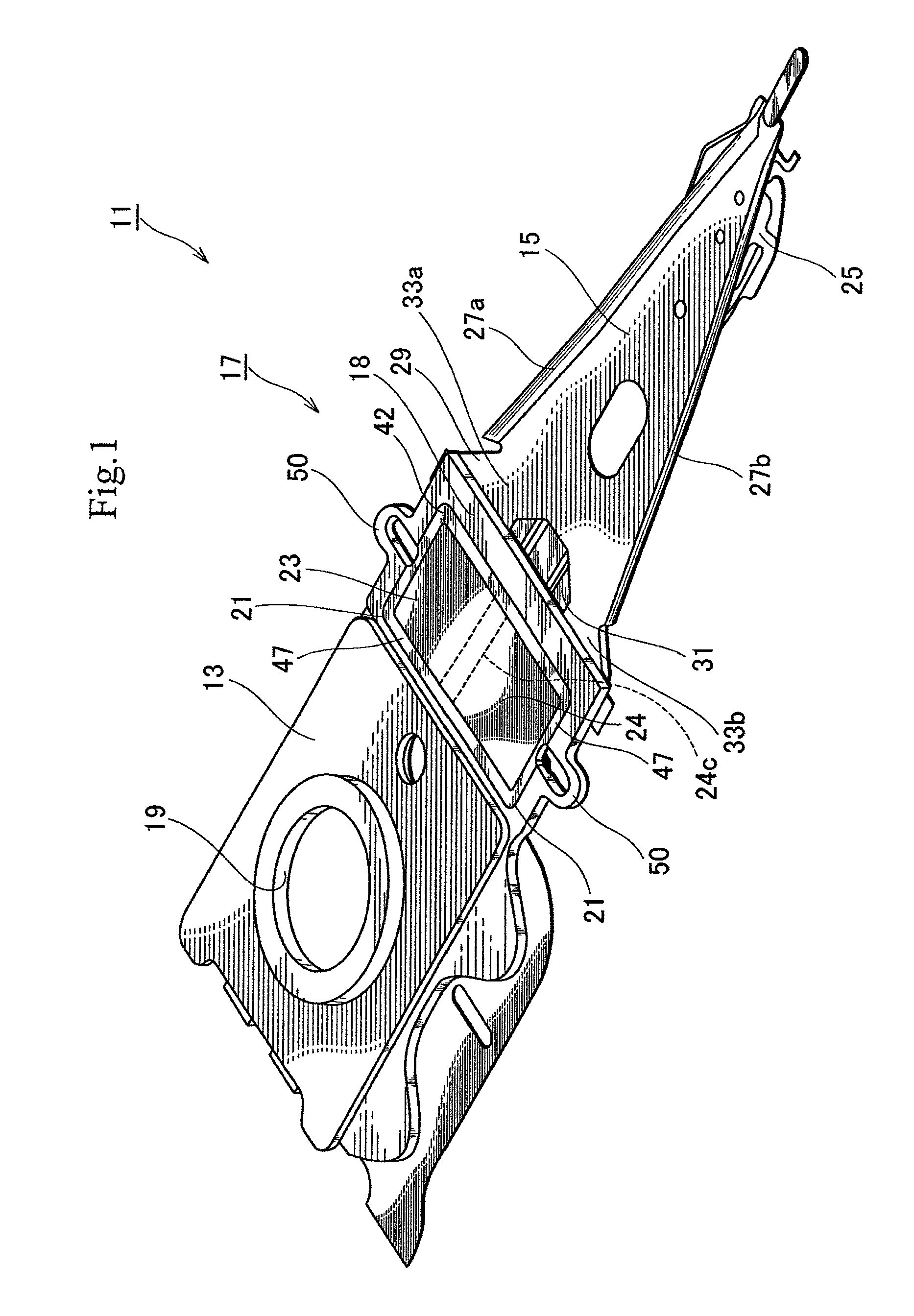
[0028]FIG. 1 is a perspective view illustrating a head suspension 11 according to the present invention. As shown in FIG. 1, the head suspension 11 has a base plate 13, a load beam 15, and a piezoelectric actuator 17.

[0029]The base plate 13 is a metal thin plate made of, for example, stainless steel and has a thickness of about 150 to 200 μm. The base plate 13 may be made of light metal such as aluminum alloy or a clad material including light metal and stainless steel. The light metal may reduce the inertia of the base plate 13, increase the resonant frequency of the head suspension 11 in a sway direction, i.e., a widthwise direction of the head suspension 11, and improve the tracing performance of the head suspension 11.

[0030]The base plate 13 has a circular boss 19. With the boss 19, the base plate 13 is attached to a front end of an actuator arm (not illustrated) and is turned by a voice coil motor (not illustrated). The base plate 13 has a front end proximate to the load beam 1...

second embodiment

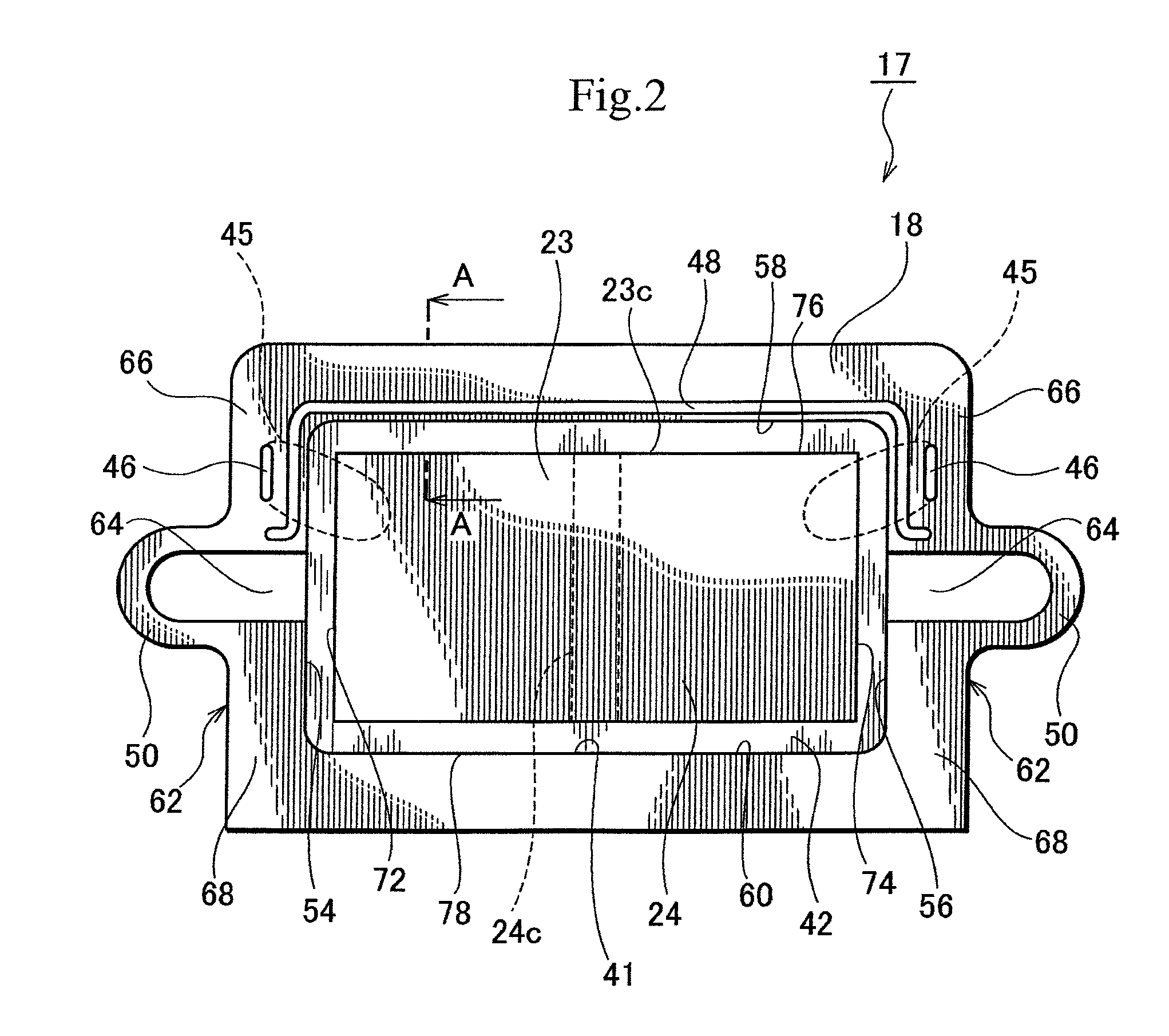
[0087]More precisely, the trap 63 is linearly formed along a front edge 58 of a circumferential edge 41 of the opening 21 in an area on a load beam 15 side of the actuator base 18. The trap 63 extends in a sway direction. There is no trap 63 along left and right edges 54 and 56 of the opening 21. That is, there is no trap 63 between the piezoelectric element 23 and conductive parts 46.

[0088]The second embodiment provides the same effect as the first embodiment. In addition, the second embodiment smoothly secures electrical connection between the piezoelectric element 23 and the conductive parts 46 without interference of the trap 63.

[0089]According to the first embodiment (FIG. 2), the trap 48 is present between the piezoelectric element 23 and the conductive parts 46, and the conductive paste 45 may flow along the trap 48.

[0090]On the other hand, the second embodiment prevents the conductive paste 45 from flowing along the trap 63.

[0091]The second embodiment is modifiable as illus...

third embodiment

[0096]The trap 73 is separated from the trap 63 by a discontinuous part 75 that is a part of an actuator base 18 of the piezoelectric actuator 71. Namely, the discontinuous part 75 separates the traps 63 and 73 from each other. At least one trap (73) is arranged between the piezoelectric element 23 and the conductive part 46. It is possible to arrange a plurality of traps between the piezoelectric element 23 and the conductive part 46. the trap 73 is longer than the conductive part 46 and is shorter than the trap 63.

[0097]The third embodiment provides the same effect as the second embodiment. In addition, the third embodiment arranges the discrete trap 73 between the piezoelectric element 23 and the conductive part 46, to improve the effect of preventing a conductive adhesive 47 from diffusing.

[0098]Since the trap 73 is separate from the trap 63, it functions to prevent a conductive paste 45 from flowing into the trap 63.

[0099]The third embodiment is modifiable as illustrated in FI...


PUM

PropertyMeasurementUnit
thicknessaaaaaaaaaa
thicknessaaaaaaaaaa
thicknessaaaaaaaaaa

Abstract

A head suspension has a load beam and a piezoelectric actuator. The piezoelectric actuator has an actuator base connected to a base part of the load beam and a piezoelectric element attached to an opening formed in the actuator base. The piezoelectric actuator displaces a front end of the load beam in a sway direction according to deformation of the piezoelectric element that occurs in response to a voltage applied thereto. The head suspension includes a nonconductive adhesive filled between the piezoelectric element and the opening, to fix the piezoelectric element to the opening and a trap formed on the actuator base outside the opening, to hold the nonconductive adhesive oozing out of the opening and prevent the oozed adhesive from spreading. The trap prevents the oozed adhesive from contaminating the periphery of the opening.

Description

BACKGROUND OF THE INVENTION[0001]1. Field of the Invention[0002]The present invention relates to a head suspension for a disk drive incorporated in an information processing apparatus such as a personal computer, and particularly, to a head suspension having a piezoelectric element that is attached thereto with a nonconductive adhesive and deforms in response to an applied voltage.[0003]2. Description of Related Art[0004]Small-sized, precision information devices are rapidly advancing, and for use with such devices, needs for micro-actuators capable of conducting positioning control for very small distances are increasing. Such micro-actuators are highly needed by, for example, optical systems for correcting focuses and inclination angles, ink jet printers for controlling ink heads, and magnetic disk drives for controlling magnetic heads.[0005]The magnetic disk drives are strongly expected to increase their storage capacities. Increasing the storage capacity of a magnetic disk drive...

Claims


Application Information

Patent Timeline
Patent Type & Authority Patents(United States)
IPC IPC(8): G11B5/56
CPCG11B5/4833G11B5/4873
Inventor IRIUCHIJIMA, OSAMUFUCHINO, HIDEKI
Owner NHK SPRING CO LTD
Why Eureka
Try Eureka