Pelvic implanted neural electrode and method for implanting same

Inactive Publication Date: 2010-11-25
RABISCHONG PIERRE +2
View PDF20 Cites 33 Cited by
  • Summary
  • Abstract
  • Description
  • Claims
  • Application Information

AI Technical Summary

Problems solved by technology

But this company closed down a few years ago and the production of this system has stopped.
The implantation of electrodes requires an open surgery with different incisions corresponding to the muscular targets, representing a potential risk of infection as well as skin scars which can be aesthetically critical.
It was observed with the two operated patients that the epimysial electrodes are relatively difficult to put in the optimal place in relation with the motor point which can be multiple in big muscles like the gluteus maximus.
It w

Method used


Image

  • Pelvic implanted neural electrode and method for implanting same
  • Pelvic implanted neural electrode and method for implanting same
  • Pelvic implanted neural electrode and method for implanting same

Examples


Embodiment Construction

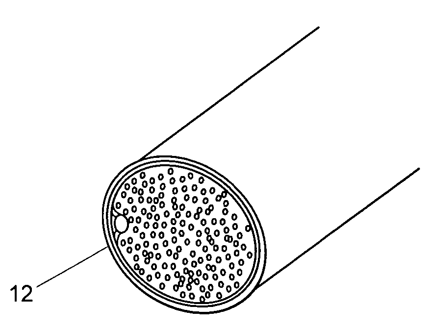
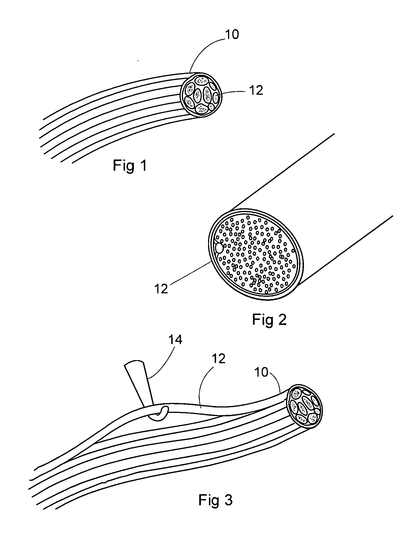
[0035]Referring now to the drawings in greater detail, a peripheral pelvic nerve bindle 10 is shown in FIG. 1 cut away to show a plurality of fascicles 12 of the nerve 10. A cross section of one fascicle 12 is shown in FIG. 2.

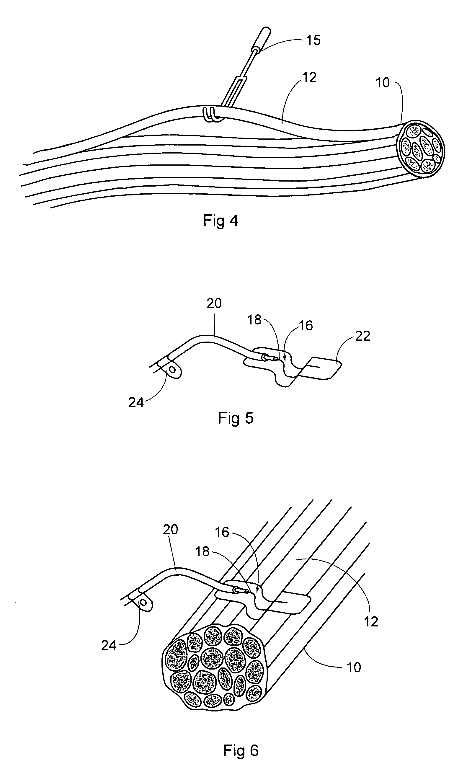
[0036]According to the teachings of the present invention individual fascicles 12 are selected from the nerve bundle 10 with a tool 14 as shown in FIG. 3 or a tool 15 as shown in FIG. 4 and supplied with a stimulus to determine which muscle it controls, i.e., the target. This process is repeated until a desired fascicle 12 is located.

[0037]Once the desired fascicle 12 is found, a monopolar electrode 16 including a bare wire conductor end 18 of an insulated wire conductor 20 fixed to a U-shaped and winged insulating base support 22 (like a BX or conduit strap in shape), as shown in FIG. 5, is positioned around the desired fascicle 12 as shown in FIG. 6. The base support 22 has the general shape of a conduit strap or clamp. A fixation clamp 24 is mounted on the w...


PUM


Abstract

The implantable monopolar electrode assembly includes a base support structure including a layer made of a nickel titanium alloy having a temperature memory. The method is directed to electro-stimulation of muscles and to a method of implanting a monopolar electrode assembly. The method includes the steps of: first performing an endoscopic approach to the nerves and then selective electro stimulation by performing a neurolysis on nerve trunks until a desired target nerve fascicle and associated muscle is located, followed by insertion of the monopolar electrode assembly adjacent the target nerve fascicle for subsequent connection to a neurposthesis system.

Description

BACKGROUND OF THE INVENTION[0001]1. Field of the Invention[0002]The present invention relates to electro-stimulation of muscles and more specifically to a monopolar electrode for such stimulation and a method of implanting such an electrode by first performing an endoscopic approach of the nerves and then selective electro stimulation by performing a neurolysis on nerve trunks.[0003]2. Description of the Prior Art[0004]Electro stimulation has been used for many years to activate muscles artificially by controlling three parameters: 1) frequency in Herz, 2) intensity in milliampere and 3) pulse width in microsecond. The clinical applications were made principally on paralysed patients from cerebral origin like in hemiplegia or from spinal cord origin like in tetraplegia (paralysis of the four limbs by cervical spine lesion) or paraplegia (lower limbs paralysis by thoracic level lesion). The electrical stimulation can be applied by electrodes placed on the skin (cutaneous), on the sur...

Claims


Application Information

Patent Timeline
IPC IPC(8): A61N1/05
CPCA61N1/0558A61N1/0556
Inventor RABISCHONG, PIERREGALLEGO, STEPHANE GERARDFRAISSE, GEORGES
Owner RABISCHONG PIERRE
Why Eureka
Try Eureka