Combination Electrical Stimulating and Infusion Medical Device and Method

a technology of electrical stimulation and infusion catheters, which is applied in the field of medical devices and infusion catheters for treating medical conditions, can solve the problems of nerve tissue in the disc to generate pain signals, limited ability of the disc to heal or regenerate, and chronic pain in many patients, so as to prevent inadvertent buckling or displacement of the lead, reduce the risk of infection, and prevent backflow of infusion material

Inactive Publication Date: 2008-01-10
VILIMS BRADLEY D
View PDF65 Cites 251 Cited by
  • Summary
  • Abstract
  • Description
  • Claims
  • Application Information

AI Technical Summary

Benefits of technology

[0019] In some embodiments of the present invention, instead of a single tubular shaped body, the stimulation lead may have a plurality of lead elements with a common base, and the stimulation elements may be selectively deployed at the targeted tissue site. The separate stimulation elements may be deployed by a number of deployment mechanisms to include spring elements, hydraulic force, and selected materials with elastomeric and resilient characteristics that expand the lead elements in the desired configuration once it is freed from within an introducer needle or sheath. In yet other embodiments of the present invention, the stimulation elements may be flat or planar as opposed to tubular shaped. In some of the embodiments, a central stylet can be used to help guide the stimulation lead and to provide some additional rigidity to prevent inadvertent buckling or displacement of the lead.
[0020] Once the stimulation lead is correctly positioned, the lead is then connected to a pulse generator for delivery of electrical energy to the electrodes located on the distal portion of the stimulation lead. The electrical circuit can be completed by either use of a grounding pad placed on the patient or by the stimulation lead itself where the electrodes are provided in various combinations of anodes and cathodes. For those embodiments that include infusion ports, the lead may also be connected to an infusion pump that provides a controlled delivery of chemicals / nutrients through the lead to the target tissue. Preferably, the electrical pulse generator and infusion pump are implanted medical devices. These pulse generator and infusion pump devices are also preferably rechargeable and refillable. Another generally desirable characteristic of pulse generators includes those having a capability to produce either constant or variable current. It is also desirable to provide electrical contacts / electrodes that are linked in series, parallel, or combinations thereof which allow selective activation of all or a selected group of the electrodes. Other desirable general characteristics for an infusion pump are those pumps which (i) control infusion material at either a constant or variable rate, and at a constant or variable pressure, or constant or variable volume, (ii) provide automatic compensation for varying infusion pressures, and (iii) have anti-back flow capability to prevent backflow of infusion material through the stimulation lead, as well as pressure safety valves to compensate for overpressure situations. Furthermore, the pump, pulse generator and stimulation lead may be coated with an antibacterial coating to decrease the risk of infection. The pulse generator and pump may also incorporate appropriate alarms to notify of infusion and stimulation failure / abnormality.
[0021] Particular embodiments of the present invention provide one or more advantages in terms of navigation of the stimulation lead, as well as placement of the infusion ports and electrodes for effectively delivering electrical and chemical treatment. More specifically, the particular shape of the stimulation lead, as well as the particular placement of the electrodes and infusion ports are especially adapted for delivering the electrical stimulation and chemical infusion to target tissue. A stiffening or support element may be incorporated in the wall of the stimulation lead to ensure the lead does not prematurely shear or otherwise structurally fail during use and removal. The stiffening element is preferably in the form of an elongate support that extends longitudinally within the wall of the stimulation lead and terminating near the distal tip of the lead.
[0022] Other embodiments of the present invention provide advantages by use of a disposable sheath that can be used in combination with a reusable stimulation lead. The disposable sheath has electrical contacts forming the electrodes of the device when used. The reusable stimulation lead is placed inside the disposable sheath wherein the electrodes of the stimulation lead make electrical contact with the electrodes of the disposable sheath. Temperature sensing elements may be incorporated in the stimulation lead, such as thermocouples or RTDs in order to measure temperature at the active electrical areas to ensure uniform lesioning, and to otherwise provide additional safety to the procedure such that excessive energy is not applied. Since the disposable sheath is in thermal / electrical contact with the inner reusable stimulation lead, accurate temperature sensing can still take place when the temperature sensing elements are incorporated on the stimulation lead. It is also contemplated that temperature-sensing elements may be incorporated on the disposable sheath wherein the bundle of conductors from the temperature sensing elements are separately routed through the sheath.
[0023] Use of the disposable sheath allows great flexibility in determining the pattern, size, and general configuration of a stimulation lead to be used in many types of different medical procedures. By providing a reusable stimulation lead, the cost in conducting a procedure is reduced since only the disposable sheath is disposed of after use and not the entire assembly.
[0024] In yet another embodiment of the invention, an inflatable member may be used with a stimulation lead such that the inflatable member can shift or adjust the exact positioning of the stimulation lead to more accurately apply the electrical or thermal energy to the targeted area.

Problems solved by technology

As a result, a disc has limited ability to heal or regenerate.
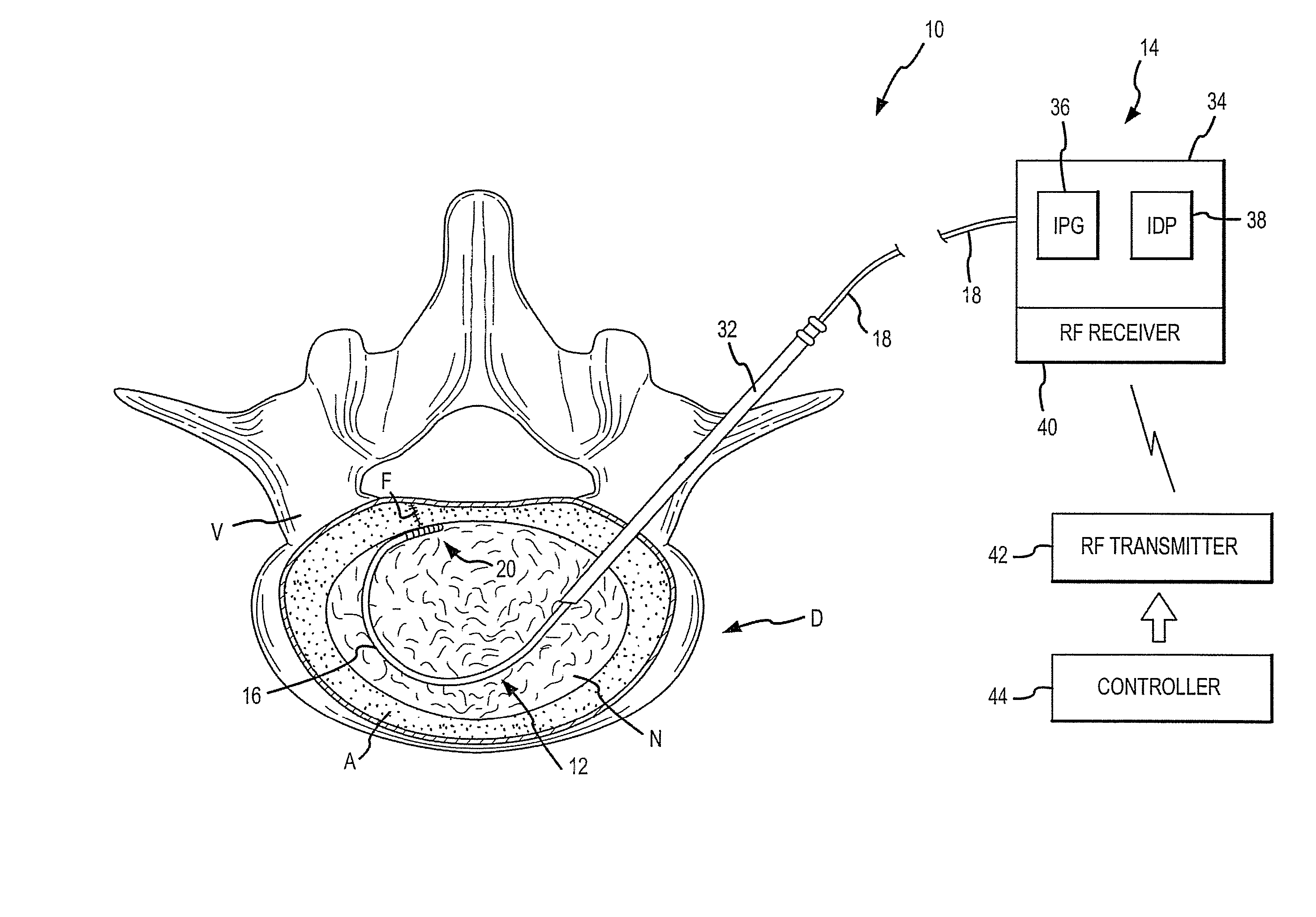
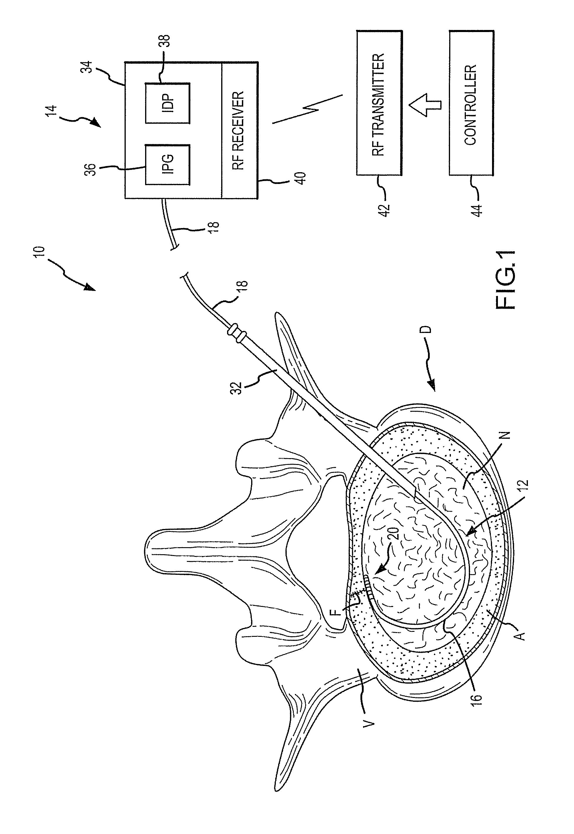
Due to age, injury or other conditions, cracks or fissures may develop in the wall of invertebral discs causing a chronic source of pain in many patients.
Additionally, the inner disc tissue (nucleus) will frequently cause the disc to bulge or herniate into the fissures in the outer region of the disc, thus causing nerve tissue therein to generate pain signals.
Success with these treatments is frequently disappointing and the patient will all too often have to undergo spinal fusion.
However, recent research, and clinical experience has cast doubt as to the exact method of action.
While these procedures have proven more effective than placebo, the results are far from acceptable.
Placement of a stimulation lead within a disc can be quite difficult.
Because a disc does not have a uniform density, known stimulation leads can be quite difficult to place and may require the attending physician to make multiple attempts for proper placement or abandon the procedure.
Of course, multiple placement attempts greatly increase the invasive nature of the procedure and therefore create unnecessary tissue damage and increased risk.
Inability to perform the procedure denies the patient a therapeutic option.
Improper placement of the stimulation lead can also result in the undesirable damage of nerve tissue that is not contributing to the chronic pain or other ailments.
Because of the overall metabolically inactive nature of the disc, it is also important that chemical infusion be precisely targeted to contact the damaged area of the disc with the delivered chemicals / nutrients, otherwise inaccurate delivery to non-damaged portions of the disc can reduce the effectiveness of the procedure.
Extensive therapy and treatment is often unsuccessful in alleviating such pain since some of these problems are actually associated with symptomatic sacroiliac dysfunction or instability.
With respect to neural ablation to alleviate symptomatic pain associated with numerous types of spine ailments, current stimulation leads are limited in the provision of ablative heat based on the size of the electrodes, their spacing along the lead, and their particular positioning relative to the targeted nerve group.
Multiple lead position changes during a procedure of course increases the invasive nature of the procedure and also introduces additional risk that multiple needle insertions will damage non-targeted tissue.

Method used


Image

  • Combination Electrical Stimulating and Infusion Medical Device and Method
  • Combination Electrical Stimulating and Infusion Medical Device and Method
  • Combination Electrical Stimulating and Infusion Medical Device and Method

Examples


first embodiment

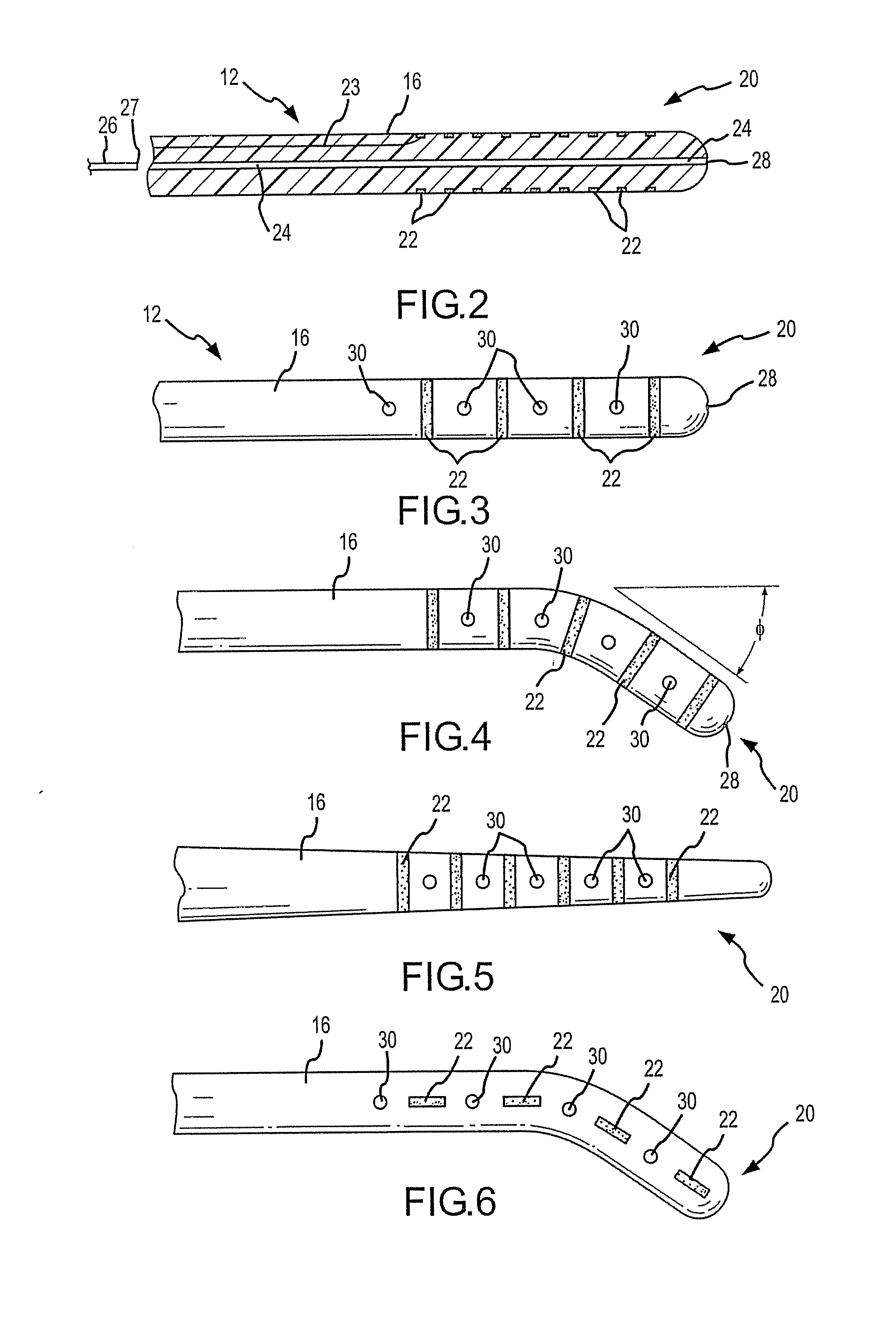
[0090] Referring specifically to FIG. 2, in the stimulation lead, a plurality of circumferentially extending electrodes 22 are positioned at the distal portion 20. The electrodes 22 are also spaced longitudinally along the distal portion 20. The electrodes produce an array of electrical field energy, and the target tissue is immersed in the electrical field. One or more electrical conductors 23 extend through the interior of the stimulation lead 16 in order to transmit the electrical impulses to the electrodes 22. It is preferable to utilize a single conductor 23 along the major length of the lead, and then provide branch conductors (not shown) at the distal portion 20 that then extend to contact the various electrodes. The branch conductors could be a linearly arranged set of wire extensions extending between each electrode, or any other advantageous combination of wire conductors to interconnect the electrodes. Use of a single conductor is a more robust design as opposed to multip...

embodiment 310

[0154] Referring to FIG. 65, this alternative sheath embodiment 310 is characterized by a very flexible body 312 having a plurality of slots or openings 314 formed therein. A distal end of the body 312 includes a tip 316. The tip can be blunt or sharp, depending upon the intended use. Referring to FIG. 66, electrodes 318 are cylindrical shaped sections that are slipped over the body 312, in the same manner as disclosed with respect to FIG. 59. However, in the case of FIG. 66, a bracket 320 is used to interconnect the electrodes from the reusable stimulation lead with the electrodes 318 formed on the sheath. As shown, the bracket 320 may include a pair of traverse flanges 322, sidewalls 326, and base 328. Accordingly, a channel 324 is formed between the sidewalls and base. The bracket 320 is placed in a corresponding slot 314 such that the flanges 322 rest on the outer surface of the body 312. When the electrode 318 is slipped over the body 312, the electrode 318 is aligned such that...


PUM


Abstract

A combined electrical and chemical stimulation lead is especially adapted for providing treatment to the spine and nervous system. The stimulation lead includes electrodes that may be selectively positioned along various portions of the stimulation lead in order to precisely direct electrical energy to ablate or electrically stimulate the target tissue. Embodiments of the stimulation lead include single or multiple lead elements. The multiple lead element embodiments can be selectively deployed to cover a targeted area. The lead may also includes central infusion passageway(s) or lumen(s) that communicates with various infusion ports spaced at selected locations along the lead to thereby direct the infusion of nutrients/chemicals to the target tissue. Some embodiments utilize a disposable sheath in combination with a reusable stimulation lead.

Description

CROSS REFERENCE TO RELATED APPLICATION [0001] This application is a continuation-in-part of co-pending application Ser. No. 11 / 678,516 filed on Feb. 23, 2007 entitled “COMBINATION ELECTRICAL STIMULATING AND INFUSION MEDICAL DEVICE”, which is a continuation-in-part of co-pending application Ser. No. 11 / 107,553, filed on Apr. 14, 2005, entitled “COMBINATION ELECTRICAL STIMULATING AND INFUSION MEDICAL DEVICE”, which is a continuation-in-part of co-pending application of application Ser. No. 11 / 033,591, filed on Jan. 11, 2005, entitled “COMBINATION ELECTRICAL STIMULATING AND INFUSION MEDICAL DEVICE”, the disclosures of which are hereby incorporated by reference herein.TECHNICAL FIELD OF THE INVENTION [0002] The present invention relates generally to electrical stimulation leads and chemical infusion catheters for treatment of medical conditions, and more particularly, to a system, method and device for providing combined electrical stimulation and chemical / drug infusion for treatment of...

Claims


Application Information

Patent Timeline
Patent Type & Authority Applications(United States)
IPC IPC(8): A61N1/04
CPCA61B18/1477A61B18/1492A61B2018/00214A61M5/14276A61M25/0043A61N1/36135A61N1/0551A61N1/0558A61N1/36017A61N1/36071A61N1/403A61M25/007
Inventor VILIMS, BRADLEY D.
Owner VILIMS BRADLEY D
Why Eureka
Try Eureka