Shock bump array

a technology of shock waves and arrays, applied in the field of shock waves, can solve problems such as ineffective shock waves

Inactive Publication Date: 2010-12-02
AIRBUS OPERATIONS LTD
View PDF33 Cites 20 Cited by
  • Summary
  • Abstract
  • Description
  • Claims
  • Application Information

AI Technical Summary

Benefits of technology

[0018]Typically the first series of shock bumps is shaped and positioned so as to modify the structure of a shock which would form adjacent to the surface of the structure in the absence of the first series of shock bumps when the structure is operated at a first condition; and the one or more shock bumps positioned aft of the first series is (are) shaped and positioned to modify the structure of a shock which would form adjacent to the surface of the structure in the absence of the one or more shock bumps positioned aft of the first series when the structure is operated at a second condition. This can be contrasted with US 2006 / 0060720 which uses a shock control protrusion to generate a shock which would not otherwise exist in the absence of the shock control protrusion.
[0019]The structure may comprise an aerofoil such as an aircraft wing, horizontal tail plane or control surface; an aircraft structure such as a nacelle, pylori or fin; or any other kind of aerodynamic structure such as a turbine blade.
[0020]In the case of an aerofoil the shock bumps may be located on a high pressure surface of the aerofoil (that is, the lower surface in the case of an aircraft wing) but more preferably the surface is a low pressure surface of the aerofoil (that is, the upper surface in the case of an aircraft wing). Also each bump in the first series typically has an apex which is positioned towards the trailing edge of the aerofoil, in other words it is positioned aft of 50% chord. The apex of the bump may be a single point, or a plateau. In the case of a plateau then the leading edge of the plateau is positioned towards the trailing edge of the aerofoil.

Problems solved by technology

However for “off-design” operating conditions the position of the shock may change, making the shock bumps ineffective.

Method used


Image

  • Shock bump array
  • Shock bump array
  • Shock bump array

Examples


second embodiment

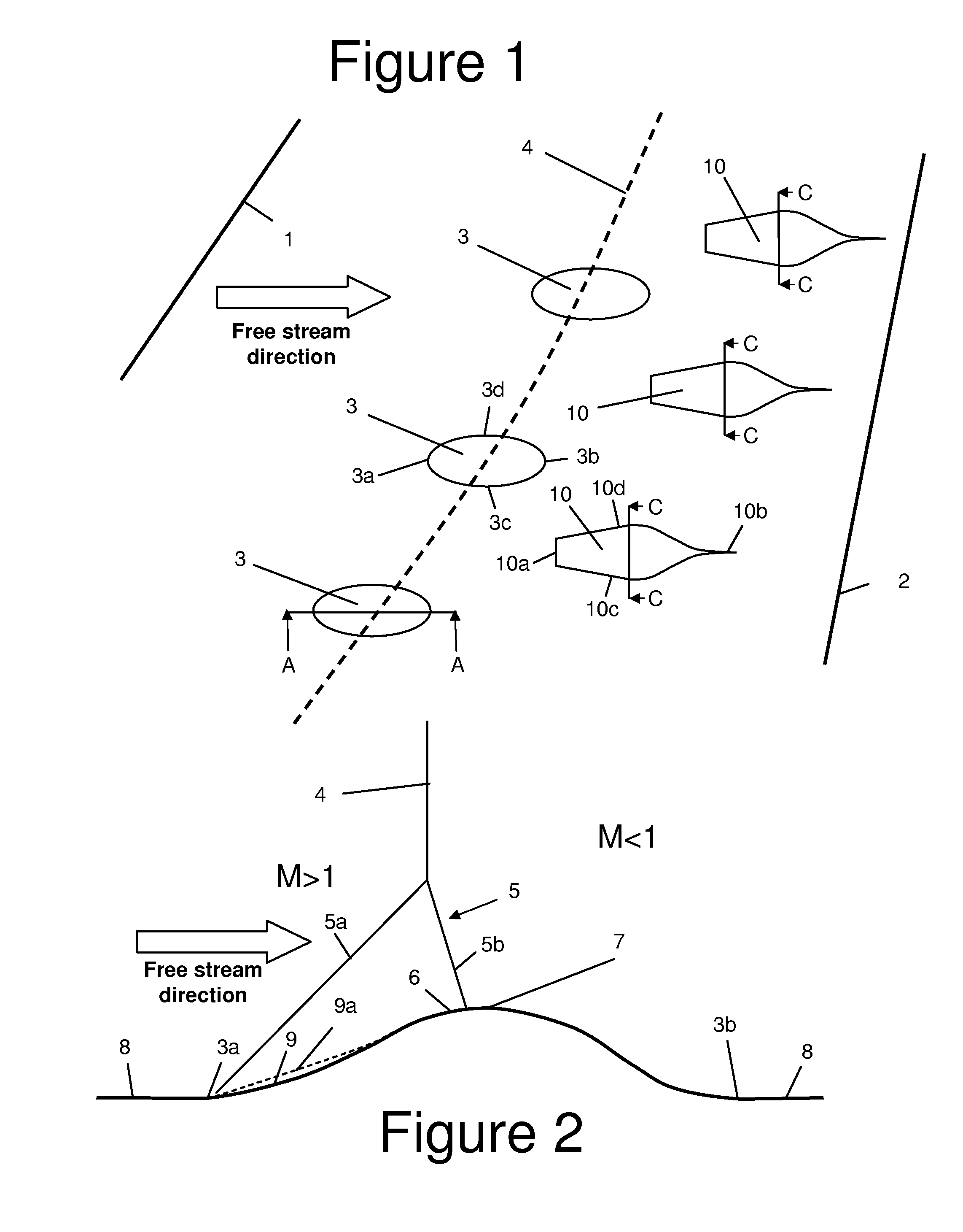
[0047]FIG. 7 is a plan view of the upper surface of an aircraft wing according to the present invention. The wing has a leading edge 1a and a trailing edge 2a, each swept to the rear relative to the free stream direction. The upper surface of the wing carries an array of shock bumps extending from its surface. The array comprises a first series of shock bumps 30a; and a second series of shock bumps 30b positioned aft of the first series.

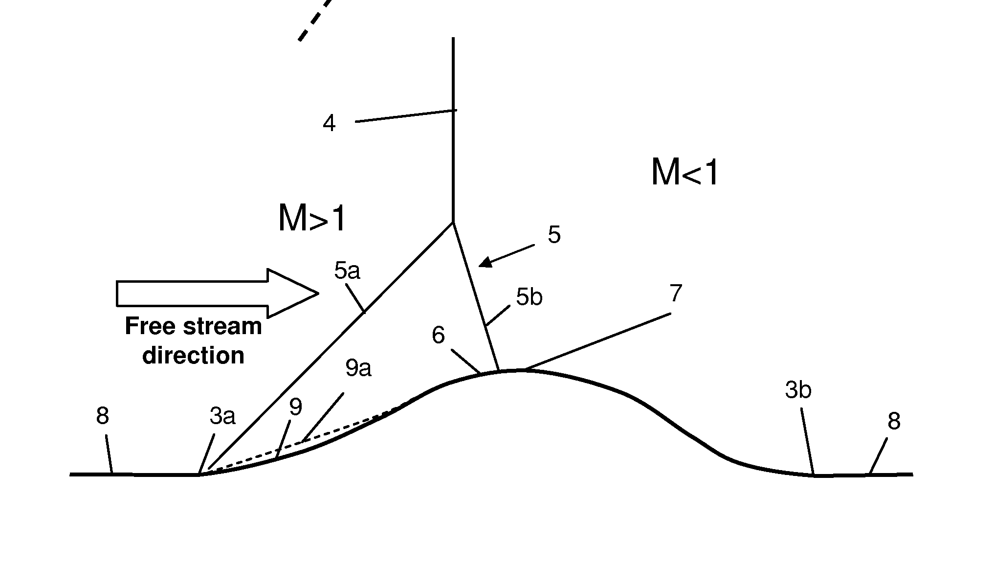
[0048]At transonic speeds a shock forms normal to the upper surface of the wing. FIG. 7 shows the position 4a of the shock when the aircraft is operated at a “design” operating condition. At this “design” operating condition the shock bumps 30a are positioned so as to induce a smeared foot in the shock 4a with a lambda like wave pattern similar to the shock foot shown in FIG. 2, and the flow over the second series of shock bumps 30a is fully attached.

first embodiment

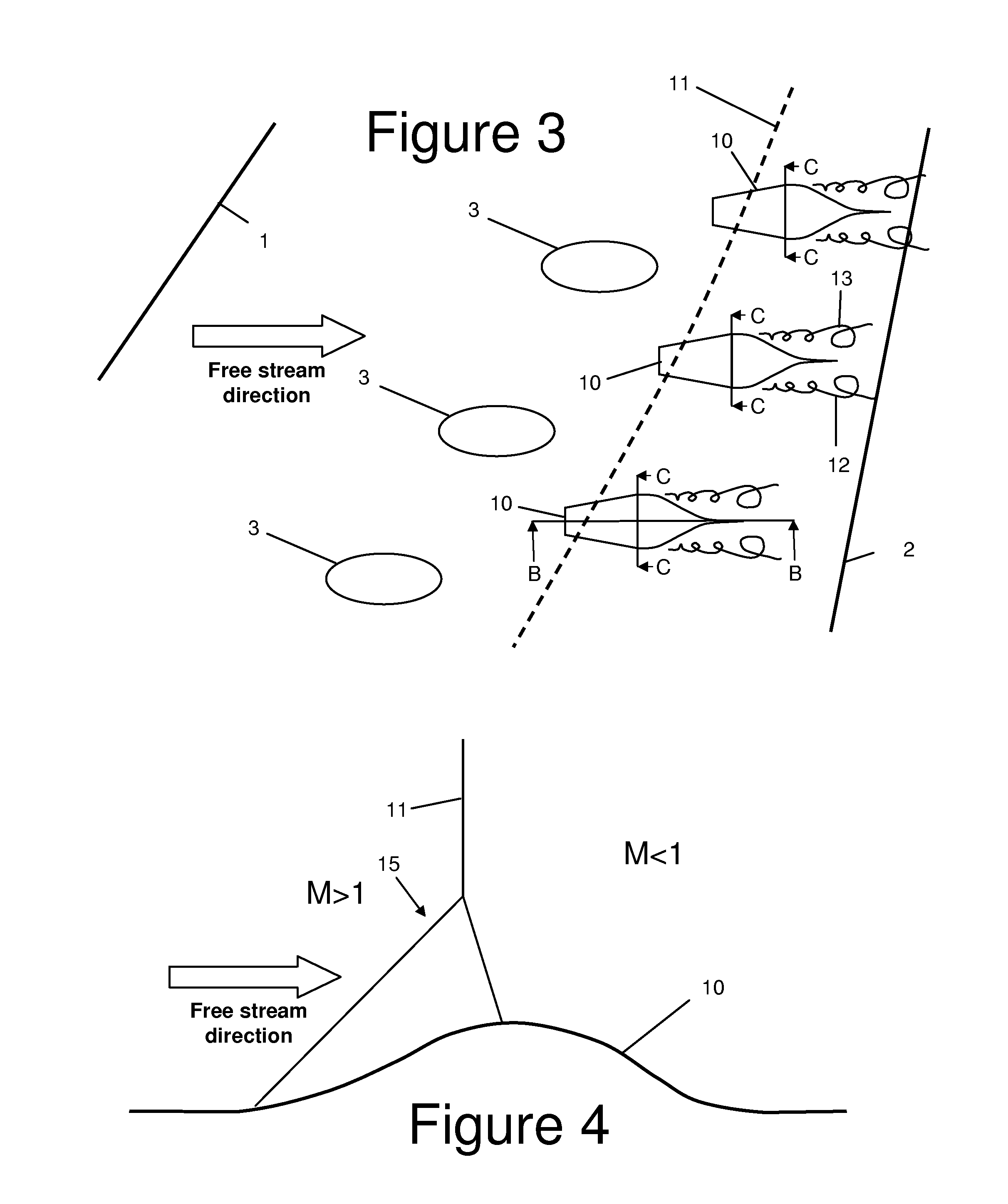
[0049]The second series of shock bumps 30b is positioned to modify the structure of a shock 11a which forms adjacent to the surface of the wing when the aerofoil is operated at a higher Mach number or lift coefficient associated with an “off-design” operating condition as shown in FIG. 8. Unlike the shock bumps in the first embodiment, the second shock bumps 30b are identical in shape to the first series of shock bumps 30a.

third embodiment

[0050]FIG. 9 is a plan view of the upper surface of an aircraft wing according to the present invention. The embodiment of FIG. 9 is identical to the embodiment of FIGS. 7 and 8, except in this case the two series of shock bumps 30a, 30b are less spaced part in a chord-wise sense, so the leading edge of the aft bumps 30b is positioned forward of the trailing edge of the adjacent forward bumps 30a so the two series partially overlap.


PUM


Abstract

An aerodynamic structure comprising an array shock bumps (3, 10) extending from its surface, the array comprising: a first series of shock bumps; and one or more shock bumps positioned aft of the first series. Preferably at least one of the one or more shock bumps positioned aft of the first series is offset so that it is not positioned directly aft of any of the shock bumps in the first series. By providing an array of shock bumps instead of a single line, the first series of shock bumps and the one or more shock bumps positioned aft of the first series can be positioned to modify the structure of a shock which forms under a different respective condition.

Description

FIELD OF THE INVENTION[0001]The present invention relates to an aerodynamic structure comprising an array of shock bumps extending from its surface; and a method of operating such a structure.BACKGROUND OF THE INVENTION[0002]As described in Holden, H.A. and Babinsky, H. (2003) Shock / boundary layer interaction control using 3D devices In: 41st Aerospace Sciences Meeting and Exhibit, Jan. 6-9, 2003, Reno, Nev., USA, Paper no. AIAA 2003-447 (referred to below as “Holden et al.”) as a transonic flow passes over a 3-D shock bump the supersonic local conditions induce a smeared shock foot with a lambda-like wave pattern.[0003]Conventionally such shock bumps are arranged in a single line which is positioned so as to modify the structure of the shock for a single operating condition. However for “off-design” operating conditions the position of the shock may change, making the shock bumps ineffective.[0004]US 2006 / 0060720 uses a shock control protrusion to generate a shock extending away fr...

Claims


Application Information

Patent Timeline
Patent Type & Authority Applications(United States)
IPC IPC(8): B64C23/04
CPCB64C23/04
Inventor WOOD, NORMAN
Owner AIRBUS OPERATIONS LTD
Why Eureka
Try Eureka