Photovoltaic Solar Island

a solar island and photovoltaic technology, applied in the field of photovoltaic islands, can solve the problems of high cost, limited large-scale implementation of energy producing systems that rely on the sun, and limited practical limitations of large-scale implementation of energy producing systems relying on the sun, so as to achieve the effect of reducing the known concerns

Inactive Publication Date: 2010-12-09
NOVATON ERNEUERBARE ENGERGIEN
View PDF18 Cites 39 Cited by
  • Summary
  • Abstract
  • Description
  • Claims
  • Application Information

AI Technical Summary

Benefits of technology

[0010]It is an object of the present invention to achieve practical and tangible progress in harnessing solar energy, to mitigate the known concerns associated with current sources of electrical energy, including the possibility of a significant energy crisis in the foreseeable future.

Problems solved by technology

Geothermal energy is a distant second possibility, but clearly at much higher costs.
However, there have been practical limitations to large-scale implementation of energy producing systems that rely on the sun.
Also, higher efficiency generally requires more expensive materials.
Still further, the manufacture of photovoltaic cells requires the use of highly toxic chemicals, which present a significant and ever-expanding environmental problem.
However, in practice the land requirements for this technology are significant.
Moreover, recent studies indicate that previously estimated electricity costs, using this technology, may have been over-optimistic.
In short, the perceived promise on this technology has not yet delivered tangible benefits, in a practical sense, either due to inefficiencies or excessive costs, and also due to the inherent limitations and variations in solar irradiation.
More specifically, these trough collectors require expensive and maintenance-intensive guidance systems to dynamically adjust the angular positions of the panels of the trough, dependent on the sun's position.
This requires expensive gear drives, and also large support structures that can withstand significant load fluctuations and other structural considerations.

Method used


Image

  • Photovoltaic Solar Island
  • Photovoltaic Solar Island
  • Photovoltaic Solar Island

Examples


Embodiment Construction

[0010]It is an object of the present invention to achieve practical and tangible progress in harnessing solar energy, to mitigate the known concerns associated with current sources of electrical energy, including the possibility of a significant energy crisis in the foreseeable future.

[0011]It is another object of this invention to facilitate the large scale generation of electrical energy via the use of solar radiation, and to do so at an economically viable cost.

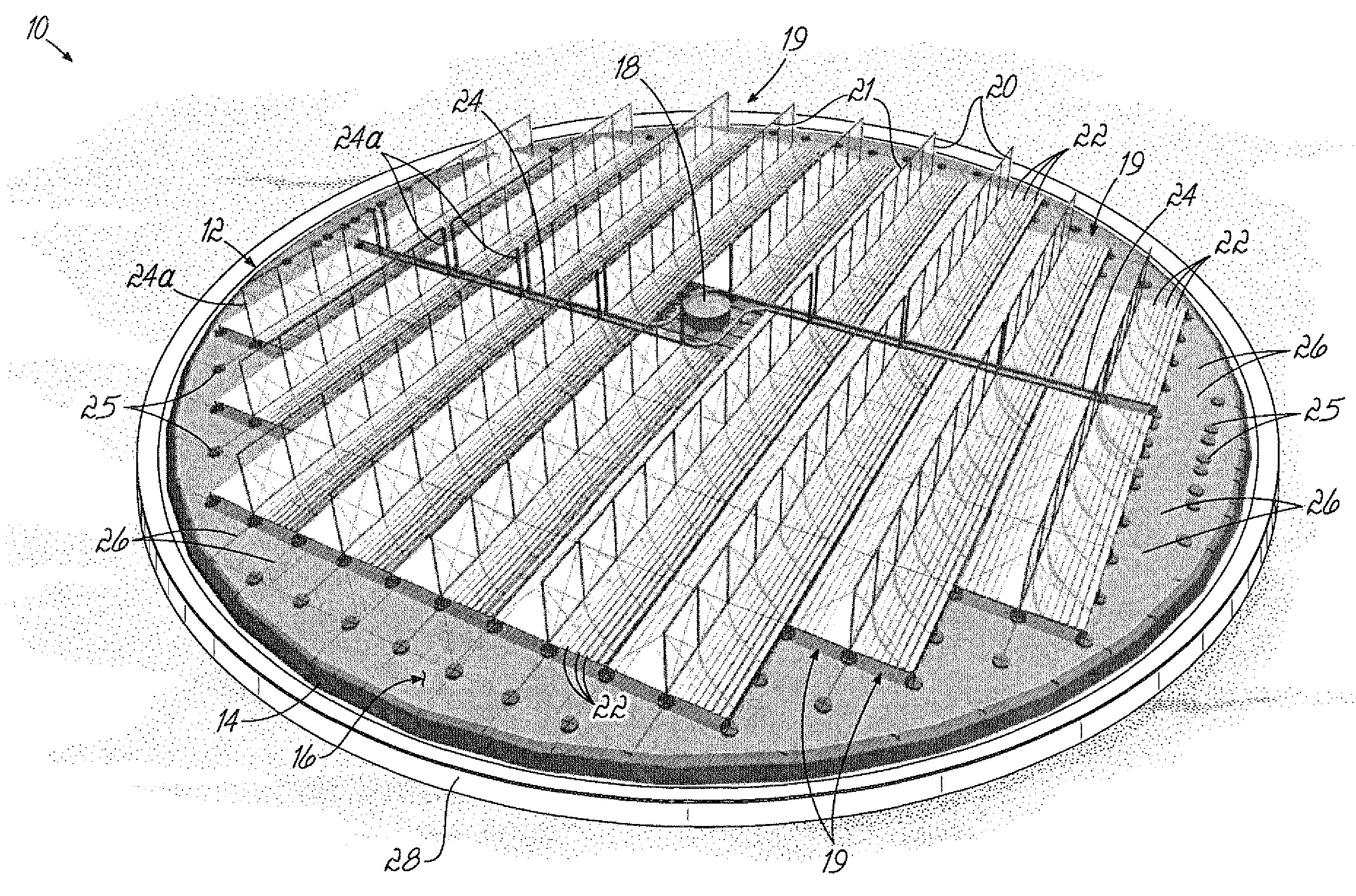
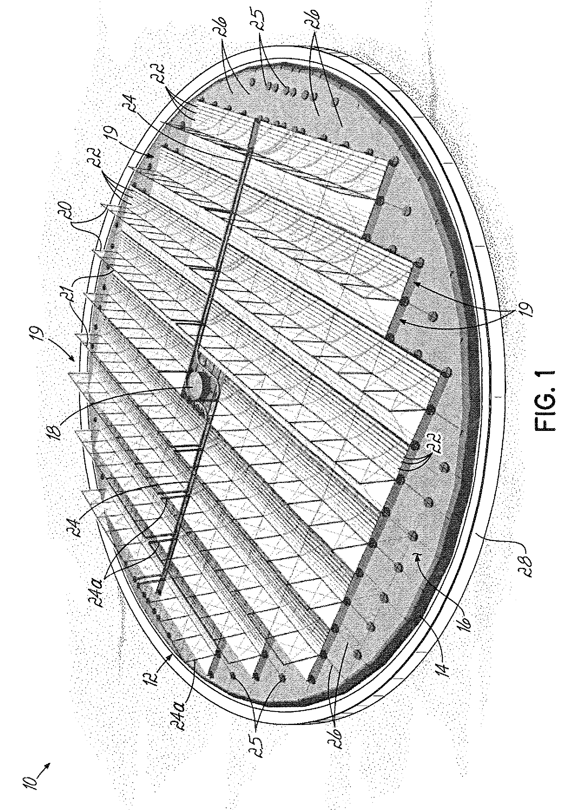
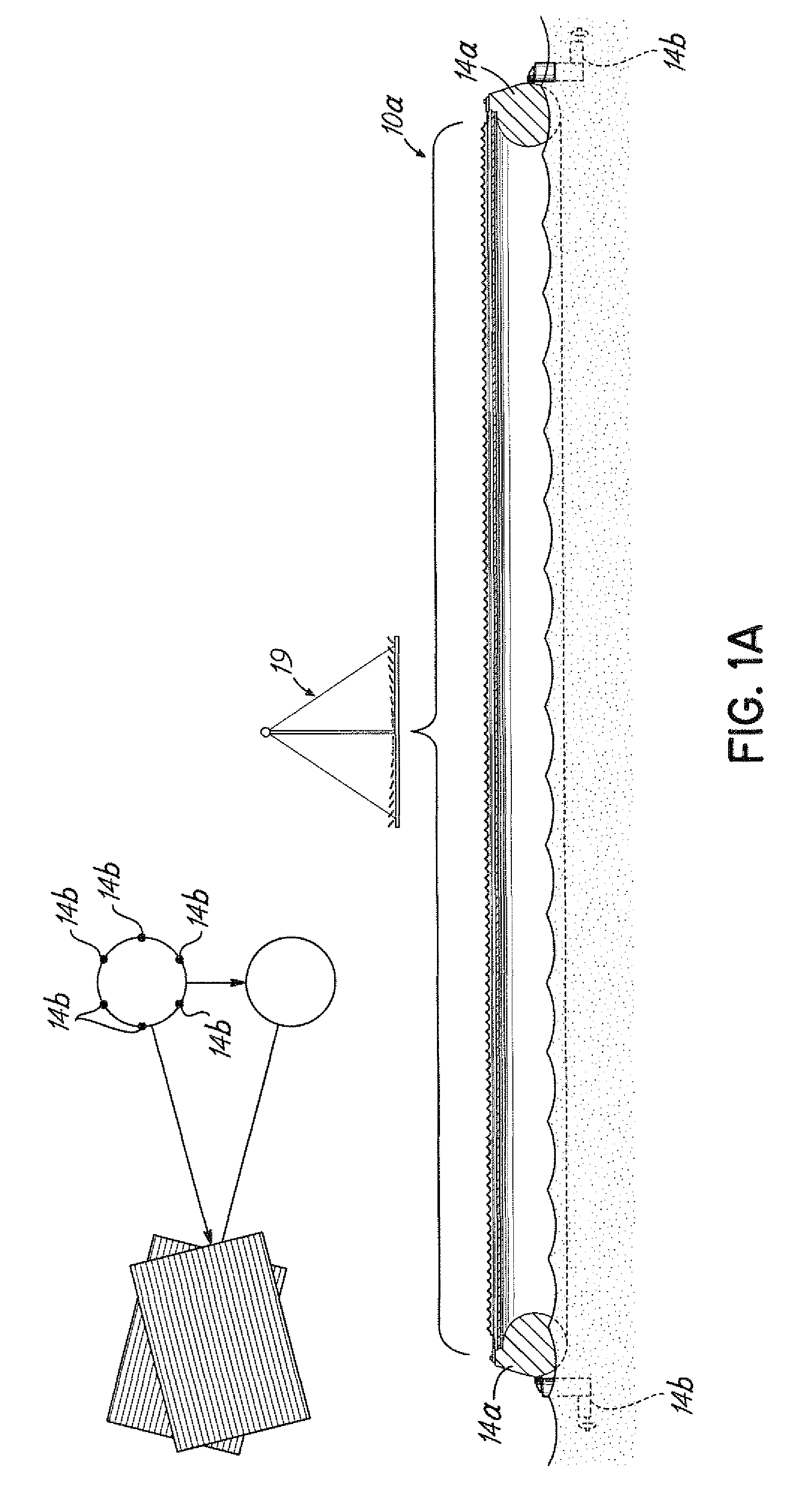
[0012]The present invention achieves these objectives by placing solar radiation collector modules on a large scale lightweight man-made island or islands that are low-cost, up to several hundred meters in diameter, and possibly even constructed with a diameter of over one kilometer. The island could either operate at sea, on large natural lakes, or on land where it would be based within a recessed trough of concrete that would hold a fluid of appropriate viscosity such as natural oil, or even water. The island floats. The...


PUM


Abstract

A man-made island [10], adaptable for land-based or sea-based operation, holds an array of photovoltaic solar collectors [421] aligned with an array of linear Fresnel lenses [422], which concentrate solar radiation on the photovoltaic solar collectors [421]. The island [10] is rotatable to optimize the angular orientation thereof relative to the position of the sun. More particularly, the man-made island [10] uses a platform [12] that includes a large outer ring [14] that floats on a fluid, and a flexible cover [16] attached to the ring [14] to define an airtight volume [30] below the cover [16]. A plurality of rows [419] of supports [420] are located above the cover [16], and carry the photovoltaic panels [421]. A compressor or blower [32] creates an over-pressure within the enclosed volume [30] to assist in supporting the cover [16] and the other components mounted thereabove. The supports [420] use brackets [431] to mount the photovoltaic panels [421] in optimum orientation relative to the lenses [422], and also support cooling device, such as fins [433], or a heat exchanger [436], or a fiber-laden conduit [437], thereby to cool the corresponding photovoltaic panels [421] and to optimize efficiency.

Description

[0001]The present application claims priority to PCT / IB2009 / 000055 filed Jan. 14, 2009, entitled “Photovoltaic Solar Island,” which claims priority to U.S. Provisional Application Ser. Nos. 61 / 021,091, filed Jan. 15, 2008, and also entitled “Photovoltaic Solar island.” Both of these applications are expressly incorporated by reference herein, in their entireties.FIELD OF THE INVENTION[0002]The present invention relates to a man-made island, either land-based or sea-based, that is equipped with solar energy collection facilities. More particularly, the present invention relates to a large scale structure of this type which is capable of producing electrical energy in a cost-effective manner.BACKGROUND OF THE INVENTION[0003]It is generally accepted that the earth is fast approaching an energy crisis of incalculable proportions. Some say that crisis will occur around the year 2040.[0004]It appears that solar power may be the only source that can theoretically overcome the upcoming ener...

Claims


Application Information

Patent Timeline
Patent Type & Authority Applications(United States)
IPC IPC(8): H01L31/052
CPCF24J2/5269Y02E10/52H01L31/0547H02S20/00Y02E10/47H02S20/32H01L31/0543H02S40/425H02S40/42B63B2035/4453F24S20/70F24S30/425F24S30/422
Inventor HINDERLING, THOMAS
Owner NOVATON ERNEUERBARE ENGERGIEN
Why Eureka
Try Eureka