Replacement structure of ratchet wrench

Active Publication Date: 2010-12-30
JIUTSANG
View PDF7 Cites 6 Cited by
  • Summary
  • Abstract
  • Description
  • Claims
  • Application Information

AI Technical Summary

Benefits of technology

[0007]The primary purpose of the present invention is to provide a ratchet wrench that facilitates effort-saving and operation smoothness in the movement of a pawl member so as to make replacement of a driving collar smooth and efficient.
[0008]Another objective of the present invention is to increase structural strength of the ratchet wrench for extending the lifespan thereof.
[0009]A further objective of the present invention is to eliminate the trouble of losing parts in order to make replacement operation easy and efficient.
[0010]To achieve the above objectives, the present invention provides a ratchet wrench, which comprises a parts replacement structure that ensures effort-sa

Problems solved by technology

A conventional ratchet wrench uses a driving collar, which is rotatably mounted in a head of the wrench and manually driven by a handle, to fit and engage a nut or a bolt and the driving collar is not removable from the wrench and is thus of a fixed size, making it not possible to meet various needs of different jobs.
However, this arrangement suffers operation problems.
This may cause jamming and abrasion between the positioning peg 27 and the circumferential positioning groove 22, leading to undesired influence on convenience of parts replacement and shortening of lifespan.
This causes clearance and improper engagement between opposing surfaces of the teeth, leading to tooth l

Method used


Image

  • Replacement structure of ratchet wrench
  • Replacement structure of ratchet wrench
  • Replacement structure of ratchet wrench

Examples


Embodiment Construction

[0022]The following descriptions are exemplary embodiments only, and are not intended to limit the scope, applicability or configuration of the invention in any way. Rather, the following description provides a convenient illustration for implementing exemplary embodiments of the invention. Various changes to the described embodiments may be made in the function and arrangement of the elements described without departing from the scope of the invention as set forth in the appended claims.

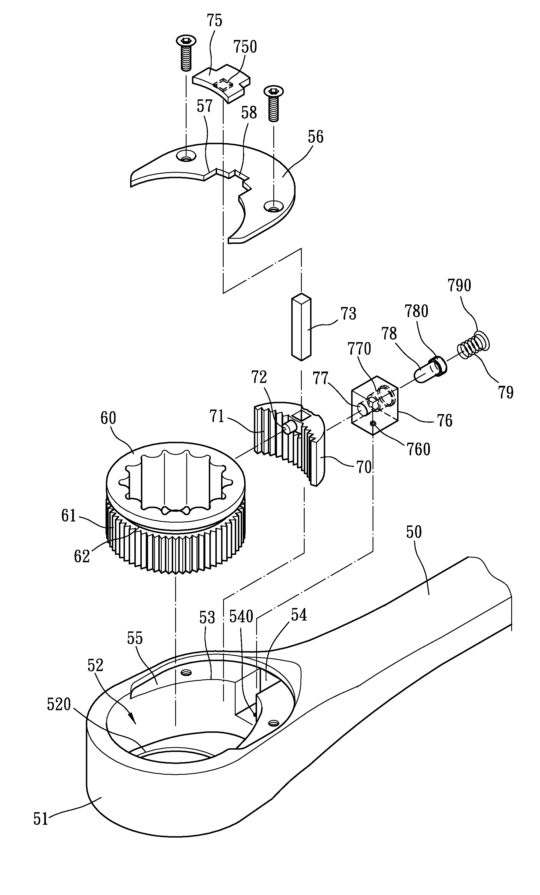
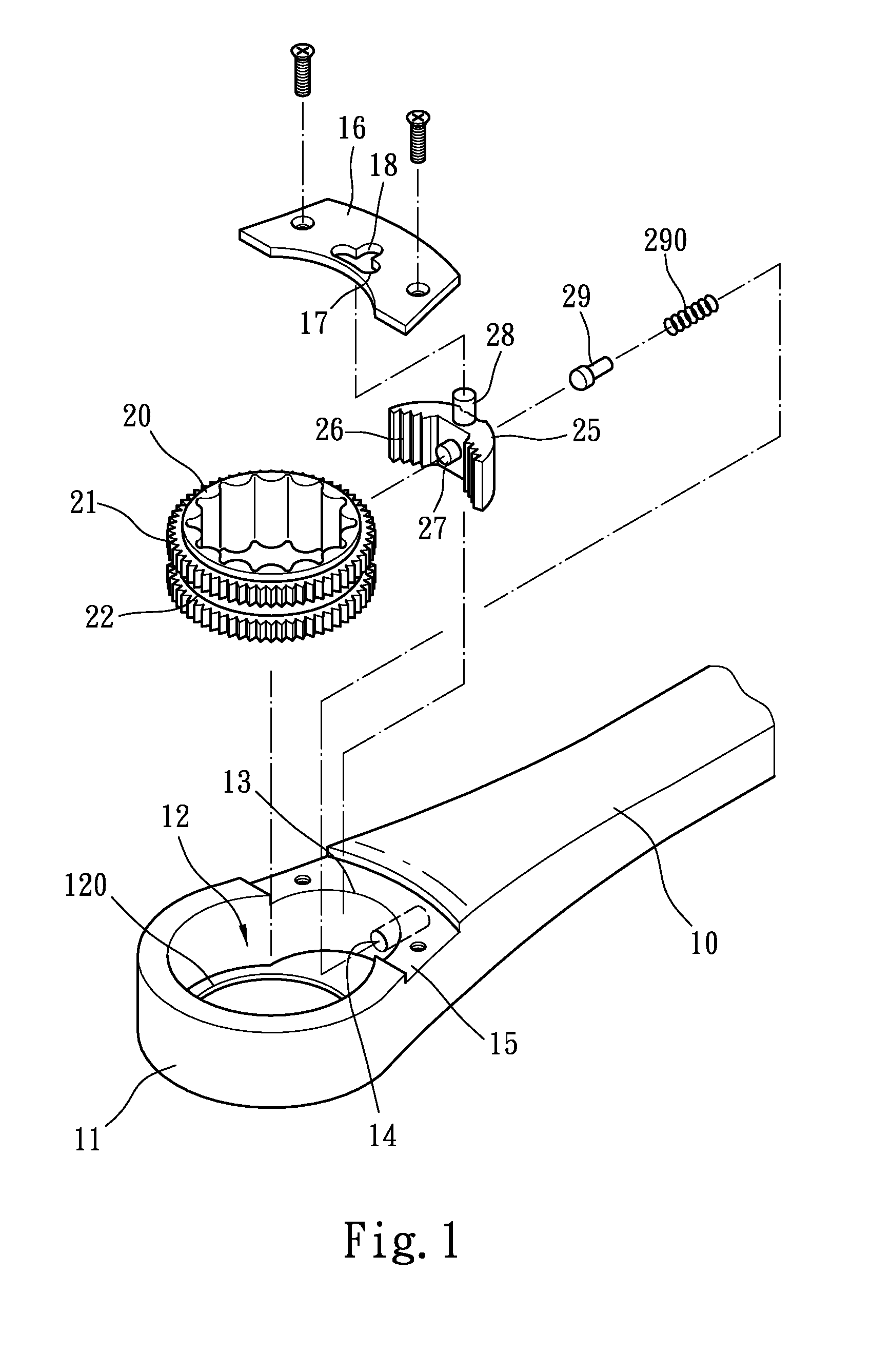
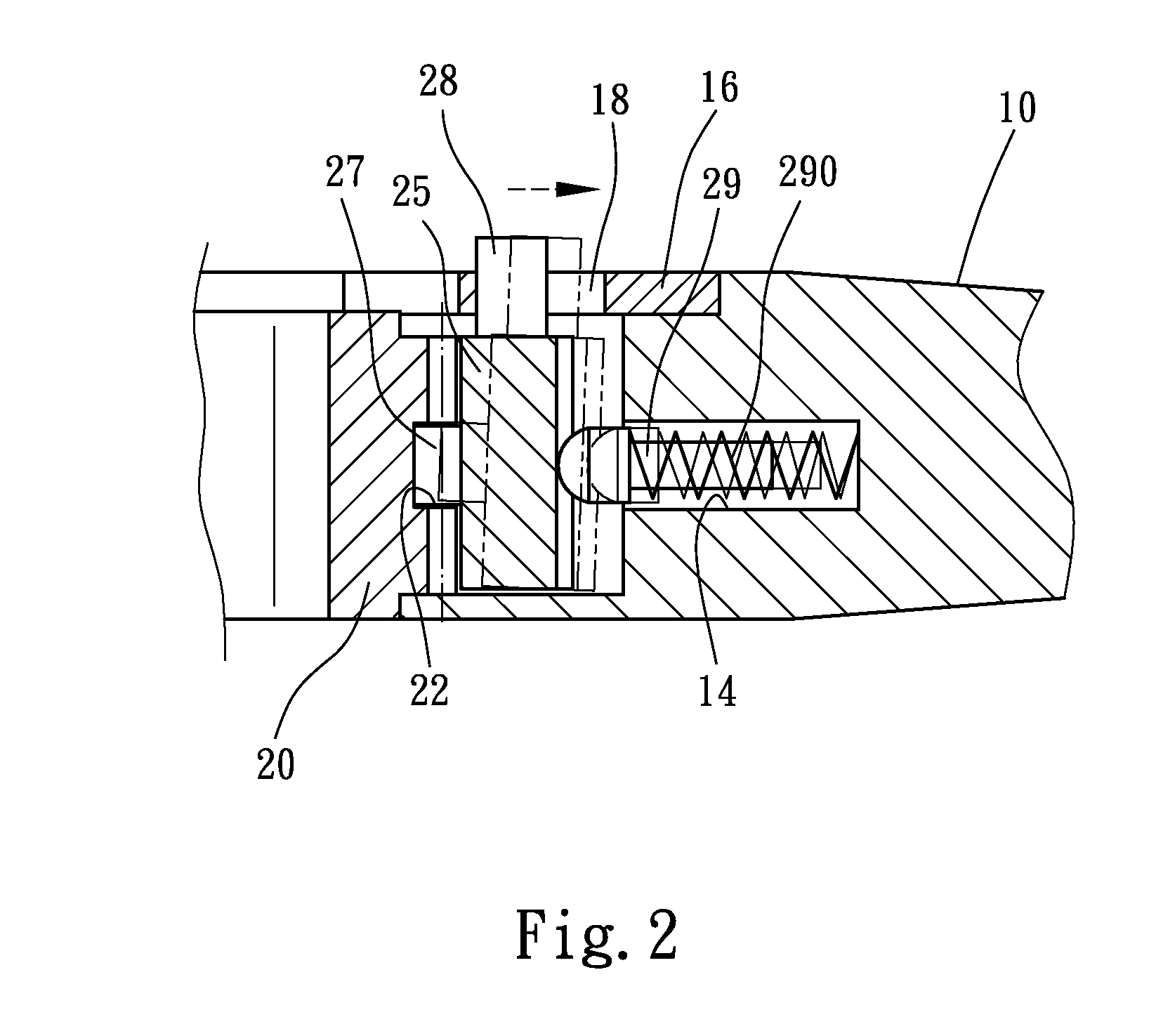
[0023]As shown in FIGS. 3-5, a ratchet wrench in accordance with the present invention comprises a handle 50, a driving collar 60, and a pawl member 70.

[0024]The handle 50 has at least one end forming a head portion 51. The head portion 51 forms a collar chamber 52. The collar chamber 52 has a bottom forming a support flange 520 and a circumferential wall forming a switching channel 53 adjacent to the handle 50. The switching channel 53 receives therein the pawl member 70. The switching channel 53 h...


PUM


Abstract

A ratchet wrench includes a parts replacement structure that ensures effort-saved and smooth operation and prevents parts from getting lost. The wrench has a handle having an end forming a head portion that rotatably receives therein a driving collar. A lid plate is fixed to the head portion to retain a pawl member that engages and controls the rotation of the driving collar. The pawl member includes a pusher pad positioned on and movable along a top of the lid plate. A retention block is set at the side of the pawl member opposite to the driving collar to apply a biasing force to the pawl member through a push bar. In this arrangement, the push bar will not get lost when the pawl member disengages from and thus releases the driving collar for replacement.

Description

TECHNICAL FIELD OF THE INVENTION[0001]The present invention generally relates to the field of ratchet wrench, and more particularly to a replacement structure of a ratchet wrench that allows ready and efficient replacement of parts of the ratchet wrench.DESCRIPTION OF THE PRIOR ART[0002]A conventional ratchet wrench uses a driving collar, which is rotatably mounted in a head of the wrench and manually driven by a handle, to fit and engage a nut or a bolt and the driving collar is not removable from the wrench and is thus of a fixed size, making it not possible to meet various needs of different jobs.[0003]Thus, a ratchet wrench with a replaceable driving collar, as shown in FIG. 1 of the attached drawings, is available in the market. The conventional ratchet wrench has a wrench handle 10 having a head portion 11 forming a recessed collar chamber 12 that rotatably receives therein a driving collar 20 having an outer circumferential surface forming ratcheting teeth 21. The collar cham...

Claims


Application Information

Patent Timeline
IPC IPC(8): B25B23/00B25B13/46
CPCB25B13/463
Inventor CHU, CHING-TSENG
Owner JIUTSANG
Why Eureka
Try Eureka